TM-9-2320-280-34 - Page 357 of 1258
TM 9-2320-280-34
6-4.
200 AMPERE ALTERNATOR (A0013036AA) TESTING AND REPAIR (Cont ’d)
c.
Cleaning
Clean all alternator components in accordance with paragraph 2-13.
d.
Assembly
NOTE
Perform steps 1 through 13 when assembling the complete
alternator.
1.
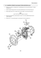
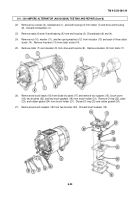
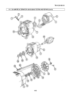
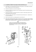
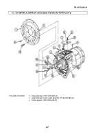
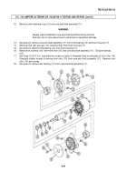
Install ground stud (3) on drive end housing (8) with lockwasher (2) and nut (1).
2.
Install seal (4) in drive end housing (8) with inner lip facing toward stator (6).
Apply thin film of grease
to lip of seal (4).
3.
Install seal (9) in drive end housing (8) with inner lip facing out from front of drive end housing (8).
Apply thin film of grease to lip of seal (9).
4.
Install insulator (5) on stator (6).
5.
Align scribe marks (7) on stator (6) and drive end housing (8) and install stator (6) in drive end housing
(8).
6.
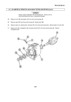
Install bearing (11) into drive end housing (8).
Ensure at least 0.156 in. (3.96 mm) clearance between
bearing (11) and drive end housing (8).
WARNING
Always support alternator rotor during installation.
Failure to do so
may cause injury to personnel or equipment damage.
CAUTION
When installing rotor shaft use caution not to damage seal.
7.
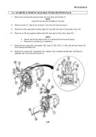
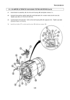
Install rotor (10) into drive end housing (8) until shoulder is against bearing (11).
8.
Install outside seal (20) flush with end housing (19) with lip facing out, away from end housing (19).
9.
Install bearing (21) into end housing (19).
Install inside seal (22) into end housing (19) with lip facing in,
toward stator (6).
10.
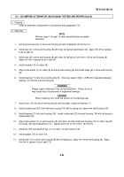
Align scribe marks (7) on end housing (19) and stator (6) and install end housing (19) on stator (6) with
four bolts (15) and lockwashers (14).
Tighten bolts (15) to 12-14 lb-ft (16-19 N m).
11.
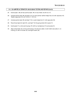
Install fan (18) and woodruff key (17) on rotor (10) with locknut (16).
12.
Install spacer (13) on rotor (10).
13.
Install seal (12) on drive end housing (8) with lip facing out, away from drive end housing (8).
Apply
thin film of grease to lip of seal (12).
6-32
Back to Top

