TM-9-2320-280-34 - Page 348 of 1258
TM 9-2320-280-34
6-4.
200 AMPERE ALTERNATOR (A0013036AA) TESTING AND REPAIR (Cont ’d)
7.
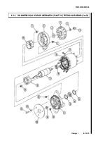
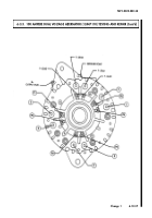
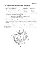
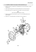
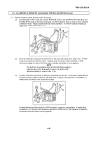
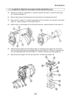
Remove two screws (20) and fuse holder (21) from drive end housing (7).
NOTE
Lead 6 will fall free when hardware is removed.
8.
Remove screw (17), lead 6 (18), and lead 1 (19) from drive end housing (7).
9.
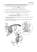
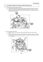
Remove nut (39), and positive rectifier leads (37) and (38) from each of three stator studs (34).
10.
Remove nut (36) and negative rectifier lead (35) from each of three stator studs (34).
NOTE
•
Spacers will fall free when diode trio is removed from drive end housing.
•
Note position of diode trio for installation.
11.
Remove three screws (26), lockwashers (25), leads 10 (24), 8 (27), 11 (28), and two brush leads (23)
from diode trio assembly (22).
12.
Remove four screws (32), lockwashers (31), washers (30), insulation washers (29), and diode trio
assembly (33) from drive end housing (7).
6-23
Back to Top

