TM-9-2320-283-13-P - Page 203 of 400
1
2
3
4
5
6
7
8
9
10
11
12
13
REMOVAL, LEFT-FRONT AIR BLOCK – CONTINUED
1
Disconnect tube (figure 7, item 2) from elbow (figure 7, item 1), and remove hose assembly
(figure 7, item 10) from reducer bushing (figure 7, item 11) on left-front bulkhead fitting mount (figure
7, item 7).
2.
Remove elbow (figure 7, item 1) and reducer bushing (figure 7, item 11) from bulkhead fitting
(figure 7, item 13).
3.
Remove nut (figure 7, item 3), lockwasher (figure 7, item 4), and bulkhead fitting (figure 7, item 13)
from left-front bulkhead fitting mount (figure 7, item 7). Discard lockwasher (figure 7, item 4).
4.
Remove locknut (figure 7, item 9), bolt (figure 7, item 5), and left-front bulkhead fitting mount
(figure 7, item 7) from spacer (figure 7, item 8) and crossmember (figure 7, item 12). Discard locknut
(figure 7, item 9).
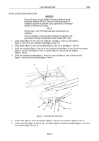
Figure 7. Left-Front Air Block.
END OF TASK
INSTALLATION, LEFT-FRONT AIR BLOCK
1.
Install left-front bulkhead fitting mount (figure 7, item 7) on crossmember (figure 7, item 12) and spacer
(figure 7, item 8) with bolt (figure 7, item 5) and new locknut (figure 7, item 9).
2.
Install bulkhead fitting (figure 7, item 13) on left-front bulkhead fitting mount (figure 7, item 7) with
new lockwasher (figure 7, item 4) and nut (figure 7, item 3).
3.
Install elbow (figure 7, item 1) and reducer bushing (figure 7, item 11) on bulkhead fitting
(figure 7, item 13).
4.
Install hose assembly (figure 7, item 10) on reducer bushing (figure 7, item 11), and connect tube (figure
7, item 2) to elbow (figure 7, item 1).
END OF TASK
TM 9-2320-283-13&P
0025
0025-5
Back to Top

