TM-9-2320-283-13-P - Page 212 of 400
TM 9-2320-283-13&P
0026
0026-4
INSTALLATION, REAR MODULATOR
WARNING
Ensure all nuts on air tube fittings are properly tightened during
installation. Refer to WP 0021. Failure to comply may result in
damage to equipment or possible injury to personnel. Seek medical
attention in the event of an injury.
NOTE
Perform steps 1 and 2 if fittings have been removed from rear
modulator.
Prior to installation, ensure pipe joint compound is applied to male
pipe threads of fittings having National Pipe Threads (NPT) only.
1.
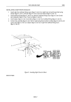
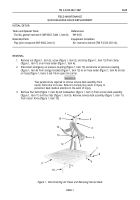
Install adapter (figure 5, item 7) on rear modulator inlet (figure 4, item 6), and install tee
(figure 5, item 13) on rear modulator outlet (figure 4, item 11).
2.
Install adapter (figure 5, item 14) and elbow (figure 5, item 12) on tee (figure 5, item 13).
3.
Install rear modulator (figure 5, item 8) on rear modulator bracket (figure 5, item 5) with two washers
(figure 5, item 10), bolts (figure 5, item 9), washers (figure 5, item 4), and new locknuts
(figure 5, item 3).
4.
Install rear modulator bracket (figure 5, item 5) on frame rail (figure 5, item 2) with two bolts
(figure 5, item 9) and new locknuts (figure 5, item 1).
1
2
3
4
5
6
7
8
9
10
11
12
13
14
15
Figure 5. Installing Rear Modulator.
5.
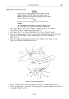
Connect tube (figure 6, item 10) to adapter (figure 6, item 9) on rear modulator (figure 6, item 1).
6.
Connect two tubes (figure 6, Items 4 and 7 ) to elbow (figure 6, item 8) and adapter (figure 6, item 1) on
rear modulator (figure 6, item 9).
Back to Top


