TM-9-2320-283-13-P - Page 210 of 400
TM 9-2320-283-13&P
0026
0026-2
REMOVAL, FRONT MODULATOR – CONTINUED
2.
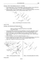
Loosen nut (figure 2, item 12) on elbow (figure 2, item 1), and disconnect tube
(figure 2, item 11) from elbow (figure 2, item 1) on frame rail (figure 2, item 2).
3.
Remove two locknuts (figure 2, item 4), washers (figure 2, item 3), bolts (figure 2, item 14), washers
(figure 2, item 13), and front modulator (figure 2, item 8) from frame rail
(figure 2, item 2). Discard locknuts (figure 2, item 4).
NOTE
Perform step 4 if front modulator will be replaced.
4.
Remove tube (figure 2, item 11) from adapter (figure 2, item 10), and remove adapter (figure 2, item 10)
from front modulator outlet (figure 2, item 9). Remove elbow (figure 2, item 6) from front modulator inlet
(figure 2, item 7).
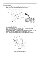
Figure 2. Removing Front Modulator.
END OF TASK
REMOVAL, REAR MODULATOR
1.
Disconnect wheel sensor cable (figure 3, item 3) from wheel sensor harness connector (figure 3, item 4)
and disconnect modulator harness connector (figure 3, item 6) from rear modulator (figure 3, item 1).
Figure 3. Disconnecting Rear Wheel Sensor and Modulator.
2.
Disconnect two tubes (figure 3, Items 5 and 7) from adapter (figure 3, item 2) and elbow
(figure 3, item 8) on rear modulator (figure 3, item 1).
3.
Disconnect tube (figure 3, item 10) from adapter (figure 3, item 9) on rear modulator (figure 3, item 1).
1
2
3
4
5
6
10
9
8
7
1
2
3
4
5
6
7
8
9
10
11
12
12
13
Back to Top

