TM-9-2320-283-13-P - Page 219 of 400
TM 9-2320-283-13&P
0027
0027-5/6 blank
INSTALLATION – CONTINUED
WARNING
Two personnel are required to remove service deck assembly from
tractor frame due to its size. Failure to comply may result in injury to
personnel. Seek medical attention in the event of injury.
9.
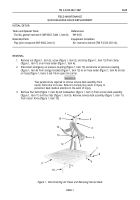
Position service deck assembly (figure 7, item 11) on tractor frame (figure 7, item 10), and install four
lockwashers (figure 7, item 7) and bolts (figure 7, item 8) on four tabs (figure 7, item 9) and service
deck assembly (figure 7, item 11).
10.
Loop strap (figure 7, item 15) around emergency air pressure hose (figure 7, item 14) and service air
pressure hose (figure 7, item 5). Install strap (figure 7, item 15) on air hose tender (figure 7, item 4) with
clamp (figure 7, item 1), screw (figure 7, item 3), and nut (figure 7, item 2).
11.
Connect emergency air pressure coupling (figure 7, item 13) and service air pressure coupling
(figure 7, item 6) to storage brackets (figure 7, item 12) on air hose tender (figure 7, item 4).
1
2
3
4
5
6
7
8
9
10
11
12
13
14
15
Figure 7. Installing Service Deck and Connecting Air Hoses.
END OF TASK
END OF WORK PACKAGE
Back to Top

