TM-9-2320-283-13-P - Page 226 of 400
TM 9-2320-283-13&P
0029
0029-2
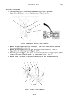
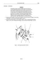
Figure 2. Removing Spring Brake Chamber.
1
2
3
4
5
6
7
8
REMOVAL – CONTINUED
WARNING
Spring brake chamber contains a loaded compression spring and
must be handled with extreme care. Be careful not to drop the spring
break chamber and always work from the side of the unit and not
from the front or back. During removal and installation, do not use
an impact wrench on the release tool or strike any part of the unit for
any reason. Do not attempt to dismantle the spring brake chamber.
Replace the entire unit if any structural damage is evident. Failure to
comply may result in damage to equipment or possible injury or
death to personnel. Seek medical attention in the event of an injury.
3.
Remove cotter pin (figure 2, item 5) from pin (figure 2, item 4) and remove pin (figure 2, item 4) from
clevis (figure 2, item 2) and slack adjuster (figure 2, item 3).
4.
Remove two locknuts (figure 2, item 6), washers (figure 2, item 7), and spring brake chamber
(figure 2, item 1) from camshaft bracket (figure 2, item 8). Discard locknuts (figure 2, item 6).
Back to Top


