TM-9-2320-283-13-P - Page 229 of 400
TM 9-2320-283-13&P
0029
0029-5
0029-5
INSTALLATION – CONTINUED
2.
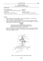
Install jamnut (figure 6, item 3) and clevis (figure 6, item 4) on pushrod (figure 6, item 2) of spring
brake chamber (figure 6, item 1) until center of holes in clevis (figure 6, item 4) are 3 in. (76 mm) from
face of spring brake chamber (figure 6, item 1). Finger tighten jamnut (figure 6, item 3).
1
2
3
4
5
6
7
8
1
2
3
4
9
Figure 6. Installing Clevis.
NOTE
Ensure spring brake chamber is installed so mounting studs are at top
of elongated holes in camshaft bracket prior to tightening locknuts.
3.
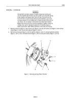
Install spring brake chamber (figure 7, item 1) on camshaft bracket (figure 7, item 8) with two washers
(figure 7, item 7) and new locknuts (figure 7, item 6).
4.
Connect clevis (figure 7, item 2) to slack adjuster (figure 7, item 3) with pin (figure 7, item 4) and new
cotter pin (figure 7, item 5). Tighten jamnut (figure 7, item 9).
5.
Un-cage spring brake chamber (figure 7, item 1). Refer to TM 9-2320-283-10.
Figure 7. Installing Spring Brake Chamber.
Back to Top


