TM-9-2320-283-13-P - Page 238 of 400
TM 9-2320-283-13&P
0032
0032-2
REMOVAL – CONTINUED
NOTE
Perform steps 2 and 3 to disconnect ABS warning light. Perform
steps 3 and 4 to disconnect ABS test switch.
Tag and note location of wires prior to removal for installation.
2.
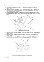
Cut black wire (figure 2, item 4) from ABS warning light (figure 2, item 1) at wire connector
(figure 2, item 5) and cut wire connector (figure 2, item 5) from blue wire (figure 2, item 6). Discard
wire connector (figure 2, item 5).
3.
Remove screw (figure 2, item 7), star washer (figure 2, item 8), black wire (figure 2, item 3), and blue
wire (figure 2, item 2) from terminal (figure 2, item 13) on ABS test switch (figure 2, item 14).
4.
Remove screw (figure 2, item 9), star washer (figure 2, item 10), and black ground wire
(figure 2, item 11) from terminal (figure 2, item 12) on ABS test switch (figure 2, item 14).
1
2
3
4
5
6
7
8
9
10
11
12
13
14
Figure 2. Disconnecting Wires.
NOTE
Perform step 5 to remove ABS warning light. Perform step 6 to
remove ABS test switch.
5.
From behind center control panel (figure 3, item 3), push housing of ABS warning light (figure 3, item 1)
out of hole (figure 3, item 2) in center control panel (figure 3, item 3).
6.
Loosen nut (figure 3, item 4) and remove collar (figure 3, item 7) and ABS test switch (figure 3, item 5)
from hole (figure 3, item 6) in center control panel (figure 3, item 3).
Back to Top


