TM-9-2320-283-13-P - Page 244 of 400
TM 9-2320-283-13&P
0033
0033-4
REMOVAL – CONTINUED
8.
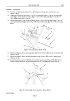
Turn two turnlock fasteners (figure 5, item 1) 90 degrees, and open center control panel (figure 5, item 2).
1
2
1
2
3
4
5
6
7
8
9
10
11
12
13
14
15
16
17
Figure 5. Opening Center Control Panel.
9.
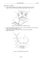
Cut black wire (figure 6, item 4) from ABS warning light (figure 6, item 1) at wire connector
(figure 6, item 5), and cut wire connector (figure 6, item 5) from blue wire (figure 6, item 6). Discard
wire connector (figure 6, item 5).
10.
Remove screw (figure 6, item 7), star washer (figure 6, item 8), black wire (figure 6, item 3), and blue
wire (figure 6, item 2) from terminal (figure 6, item 16) on ABS test switch (figure 6, item 17).
11.
Remove screw (figure 6, item 9), star washer (figure 6, item 10), and black ground wire (figure 6, item 13)
from terminal (figure 6, item 15) on ABS test switch (figure 6, item 17).
12.
Remove nut (figure 6, item 11), star washer (figure 6, item 12), and black ground wire (figure 6, item 13)
from heater control box mounting stud (figure 6, item 14).
Figure 6. Disconnecting Harness Leads from ABS Warning Light and Test Switch.
Back to Top


