TM-9-2320-283-13-P - Page 249 of 400
TM 9-2320-283-13&P
0033
0033-9
INSTALLATION – CONTINUED
14.
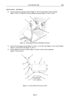
Connect speed sensor harness connector (figure 14, item 4) and modulator harness connector
(figure 14, item 1) to ABS ECU harness bulkhead connectors (figure 14, items 2 and 3).
1
2
3
4
1
2
3
4
5
6
7
8
9
10
~
Figure 14. Connecting Harnesses to Bulkhead Connectors.
15.
Connect three black ground wires (figure 15, items 2, 9, and 10) to ECU (figure 15, item 3) and firewall
(figure 15, item 8) with screw (figure 15, item 1).
16.
Connect ABS ECU harness connectors (figure 15, items 5 and 6) to ECU receptacles
(figure 15, items 4 and 7).
Figure 15. Connect ABS ECU Harness to ECU.
Back to Top


