TM-9-2320-283-13-P - Page 241 of 400
0033-1
TM 9-2320-283-13&P
0033
FIELD MAINTENANCE
ABS ECU AND DIAGNOSTIC CONNECTOR HARNESS REPLACEMENT
Tools and Special Tools
Tool kit, general mechanic’s (WP 0063, Table 2, Item 8)
Materials/Parts
Tie straps (WP 0067, Item 10)
Two wire connectors (WP 0066, Item 11)
Four locknuts (WP 0041, Item 5)
References
TM 9-2320-283-10
TM 9-2320-283-20
Equipment Condition
Battery power disconnected (TM 9-2320-283-20).
Hood raised and secured (TM 9-2320-283-10).
1
2
3
4
INITIAL SETUP:
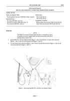
Figure 1. Disconnecting ABS ECU Harness from Battery Power.
REMOVAL
NOTE
The ABS ECU harness 30-amp fused red wire is connected to circuit
40 purple wire and is located under the instrument panel to the left of
steering column above ECU.
1.
Locate ABS ECU 30-amp fused red wire (figure 1, item 4) and follow it to black fuse connector
(figure 1, item 1) near circuit 40 purple wire (figure 1, item 3).
2.
Cut and discard wire connector (figure 1, item 2) from 30-amp fused red wire (figure 1, item 4) and
circuit 40 purple wire (figure 1, item 3).
Back to Top


