TM-9-2320-283-13-P - Page 239 of 400
TM 9-2320-283-13&P
0032
0032-3
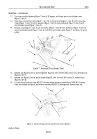
Figure 3. Removing ABS Warning Light and Test Switch.
END OF TASK
INSTALLATION
NOTE
The ABS test switch is installed by threading nut on switch housing
first. Position switch through mounting hole, install collar until tight,
and turn nut on switch housing until tight against back of panel.
1.
Install ABS test switch (figure 3, item 5) on hole (figure 3, item 6) in center control panel
(figure 3, item 3) with nut (figure 3, item 4) and collar (figure 3, item 7).
2.
Install ABS warning light (figure 3, item 1) on hole (figure 3, item 2) in center control panel
(figure 3, item 3) by pushing housing of ABS warning light (figure 3, item 1) through hole
(figure 3, item 2) until collar is against front surface of center control panel (figure 3, item 3).
NOTE
Perform steps 3 and 4 to connect ABS test switch. Perform steps 4
and 5 to connect ABS warning light.
3.
Connect black ground wire (figure 2, item 11) to terminal (figure 2, item 12) on ABS test switch
(figure 2, item 14) with star washer (figure 2, item 10) and screw (figure 2, item 9).
4.
Connect blue wire (figure 2, item 2) and black wire (figure 2, item 3) to terminal (figure 2, item 13) on
ABS test switch (figure 2, item 14) with star washer (figure 2, item 8) and screw (figure 2, item 7).
NOTE
Wire connectors shall be crimped and heat shrunk during installation.
5.
Connect black wire (figure 2, item 4) from ABS warning light (figure 2, item 1) to blue wire
(figure 2, item 6) with new wire connector (figure 2, item 5).
1
2
3
4
5
6
7
REMOVAL – CONTINUED
Back to Top


