TM-9-2320-283-13-P - Page 232 of 400
TM 9-2320-283-13&P
0030
0030-2
REMOVAL – CONTINUED
NOTE
The ABS ECU harness 5-amp fused orange wire is connected to
circuit 12C terminal stud on CB#3, located behind the circuit breaker
panel.
4.
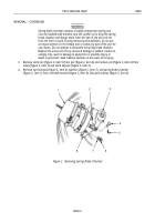
Turn three turnlock fasteners (figure 2, item 5) 90 degrees and hinge open circuit breaker cover
(figure 2, item 1).
5.
Open glove compartment door (figure 2, item 10) to glove compartment (figure 2, item 8) and remove
two screws (figure 2, item 7) and star washers (figure 2, item 6) from dash panel (figure 2, item 9) and
circuit breaker panel (figure 2, item 4).
6.
Remove screw (figure 2, item 2) and star washer (figure 2, item 3) from dash panel (figure 2, item 9)
and circuit breaker panel (figure 2, item 4) and lift circuit breaker panel (figure 2, item 4) out to access
wiring.
1
2
3
4
5
6
7
8
9
10
~
Figure 2. Circuit Breaker Panel.
7.
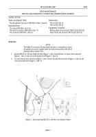
Locate ABS ECU 5-amp fused orange wire (figure 3, item 4) and follow it to black fuse connector
(figure 3, item 5) near CB#3 (figure 3, item 1).
8.
Pull cover (figure 3, item 2) off fuse connector (figure 3, item 5) and remove fuse (figure 3, item 3)
from fuse connector (figure 3, item 5).
9.
Examine fuse (figure 3, item 3). Discard fuse (figure 3, item 3) if center wire is burned away.
Back to Top


