TM-9-2320-283-13-P - Page 228 of 400
TM 9-2320-283-13&P
0029
0029-4
INSTALLATION
WARNING
Spring brake chamber contains a loaded compression spring and
must be handled with extreme care. Be careful not to drop the spring
break chamber and always work from the side of the unit and not
from the front or back. During removal and installation, do not use
an impact wrench on the release tool or strike any part of the unit for
any reason. Do not attempt to dismantle the spring brake chamber.
Replace the entire unit if any structural damage is evident. Failure to
comply may result in damage to equipment or possible injury or
death to personnel. Seek medical attention in the event of an injury.
NOTE
Installation of spring brake chambers on right and left-hand sides of
rear-rear axle is the same. This task covers the right-hand side.
Prior to installation, ensure pipe joint compound is applied to male
pipe threads of NPT fittings only.
Perform steps 1 and 2 if elbows and clevis have been removed.
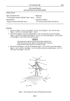
1.
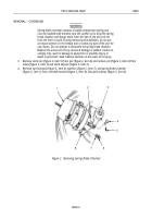
Install elbow (figure 5, item 5) on parking brake port (figure 5, item 1) and install elbow
(figure 5, item 4) on service brake port (figure 5, item 3) of spring brake chamber (figure 5, item 2).
1
3
5
2
4
Figure 5. Installing Elbows.
Back to Top


