TM-9-2320-283-13-P - Page 245 of 400
TM 9-2320-283-13&P
0033
0033-5
REMOVAL – CONTINUED
13.
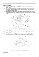
Turn three turnlock fasteners (figure 7, item 5) 90 degrees, and hinge open circuit breaker cover
(figure 7, item 1).
14.
Open glove compartment door (figure 7, item 10) to compartment (figure 7, item 8), and remove two
screws (figure 7, item 7) and star washers (figure 7, item 6) from dash panel (figure 7, item 9) and
circuit breaker panel (figure 7, item 4).
15.
Remove screw (figure 7, item 2) and star washer (figure 7, item 3) from dash panel (figure 7, item 9)
and circuit breaker panel (figure 7, item 4), and lift circuit breaker panel (figure 7, item 4) out to access
wiring.
1
2
3
4
5
6
7
8
9
10
~
1
2
3
4
5
6
Figure 7. Removing Circuit Breaker Panel.
16.
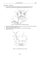
Remove nut (figure 8, item 2) and orange wire (figure 8, item 3) from CB#3, circuit 12C, terminal stud
(figure 8, item 1).
17.
Remove nut (figure 8, item 4) and blue wire (figure 8, item 5) from CB#3, circuit 38, terminal stud
(figure 8, item 6).
18.
Cut and discard tie straps from ABS ECU harness where necessary, carefully pull ABS ECU harness
leads from behind dash panel, and remove complete ABS ECU and diagnostic harness from cab.
Figure 8. Disconnecting Harness Leads from Circuit Breaker.
END OF TASK
Back to Top


