TM-9-2320-283-13-P - Page 254 of 400
TM 9-2320-283-13&P
0034
0034-4
INSTALLATION
NOTE
There are two ABS harnesses: the speed sensor harness and
modulator harness. Each harness contains four leads and each lead is
labeled with a white band denoting its location: LF, RF, LR, or RR.
Ensure ends of all harness leads are identified prior to installation.
1.
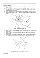
Lay out speed sensor harness (figure 5, item 5) and modulator harness (figure 5, item 8) on shop floor.
Tie together with five new tie straps (figure 5, item 6) approximately 3 ft (91 cm) from connectors
(figure 5, items 1 and 4).
2.
Connect speed sensor harness connector (figure 5, item 4) and modulator harness connector
(figure 5, item 1) to bulkhead connectors (figure 5, items 2 and 3), and route harness leads down to left
frame rail (figure 5, item 7).
1
2
3
4
5
6
7
8
Figure 5. Connecting Harnesses to Bulkhead Connectors.
WARNING
Ensure harness leads are routed to the correct wheel as labeled with
white bands denoting LF, RF, LR, or RR. Failure to comply may
result in damage to equipment and possible death to personnel. Seek
medical attention in the event of injury.
3.
Route ends of speed sensor harness (figure 6, item 1) and modulator harness (figure 6, item 2) to left
front, right front, left rear, and right rear locations as depicted in figure 6.
NOTE
When securing harnesses it is necessary to loop back excess length of
wiring and secure it with tie straps. Do not cut and splice harness
wiring together to shorten.
4.
Secure sensor harness (figure 6, item 1) and modulator harness (figure 6, item 2) with new tie straps
during installation along chassis frame.
Back to Top


