TM-9-2320-283-13-P - Page 255 of 400
TM 9-2320-283-13&P
0034
0034-5
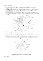
Figure 6. Connecting Rear Wheel Sensor and Modulator Harnesses.
NOTE
Connecting harness leads to wheel sensor cables and modulators is
performed the same way. The left rear and left front modulator and
wheel sensor cables are shown.
5.
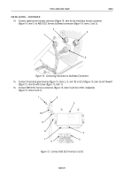
Route wheel sensor cable (figure 7, item 2) up to frame rail (figure 7, item 3) and behind left rear
modulator mounting bracket (figure 7, item 1).
1
2
2
1
2
1
2
1
1
2
3
INSTALLATION – CONTINUED
Figure 7. Routing Wheel Sensor Cable
Back to Top


