TM-9-2320-283-13-P - Page 246 of 400
TM 9-2320-283-13&P
0033
0033-6
INSTALLATION
1.
Position ABS ECU and diagnostic harness in cab.
NOTE
Circuit 38 terminal stud has two green wires connected to it.
2.
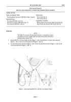
Route 36 in. (91 cm) blue wire (figure 9, item 6) from ABS warning light to circuit breaker panel
(figure 9, item 2), and connect blue wire (figure 9, item 6) to CB#3, circuit 38, terminal stud
(figure 9, item 7) with nut (figure 9, item 5).
NOTE
Circuit 12C terminal stud has a buss bar and one red wire connected
to it.
3.
Route 102 in. (91 cm) 5 Amp-fused orange wire (figure 9, item 4) from ABS ECU harness to circuit
breaker panel (figure 9, item 2), and connect orange wire (figure 9, item 4) to CB#3, circuit 12C,
terminal stud (figure 9, item 1) with nut (figure 9, item 3).
1
2
3
4
5
6
7
Figure 9. Connecting ABS ECU Harness to CB#3.
4.
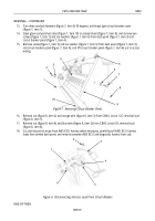
Position circuit breaker panel (figure 10, item 4) in place on dash panel (figure 10, item 9), and install
star washer (figure 10, item 3) and screw (figure 10, item 2) on dash panel (figure 10, item 9) and circuit
breaker panel (figure 10, item 4).
5.
From glove compartment (figure 10, item 8), install two star washers (figure 10, item 6) and screws
(figure 10, item 7) on dash panel (figure 10, item 9) and circuit breaker panel (figure 10, item 4). Close
and secure glove compartment door (figure 10, item 10).
6.
Close circuit breaker cover (figure 10, item 1) and turn three turnlock fasteners (figure 10, item 5)
90 degrees.
Back to Top


