TM-9-2320-328-13-P-1 - Page 1229 of 1318
TM 9-2320-328-13&P-1
0108-11/(12 blank)
DRAFT
0108
Change 1
END OF TASK
FOLLOW-ON MAINTENANCE
1.
Install driver side light bezel covers if removed (WP 0335)
2.
Remove wheel chocks (TM 9-2320-422-10)
END OF TASK
END OF WORK PACKAGE
.
.
.
.
.
.
.
.
.
.
.
.
.
.
.
.
.
.
.
.
.
.
.
.
.
.
.
.
.
.
.
.
.
.
.
.
.
.
.
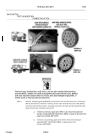
HWT3272
.
Step 12.
Put DRIVER SCENE switch to off position (WP 0004).
Turn Service Drive Lights Off
(TM 9-2320-422-10).
Pull battery disconnect switch to off position (WP 0007).
Remove
driver side rear light bezel cover (WP 0335).
Disconnect driver side body wire harness
4-pin connector.
Push battery disconnect switch to on position (WP 0007).
Turn
Service Drive Lights On (TM 9-2320-422-10).
Put DRIVER SCENE switch to on
position (WP 0004).
With a test lead set, check for 22 to 28 VDC between wire 1696
(black) from lower driver side body wire harness 4-pin connector, terminal 4 to a known
good ground.
.
a.
If there is continuity, repair wire 1696 in upper driver side body wire
harness if repairable (TM 9-2320-325-14&P), or replace driver side
body wire harness (WP 0286).
.
b.
If there is no continuity, repair wire 1696 in lower driver side body wire
harness if repairable (TM 9-2320-325-14&P), or replace driver side
body wire harness (WP 0286).
.
MALFUNCTION
TEST OR INSPECTION
CORRECTIVE ACTION
Back to Top


