TM-9-2320-328-13-P-1 - Page 133 of 1318
TM 9-2320-328-13&P-1
0017-3
DRAFT
0017
(1)
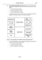
Fuel Level.
The fuel level shall be displayed in a digital format ranging from 0% to 100%.
The increments shall be in 5% increments or the minimum resolution possible.
The fuel level
shall initiate a warning light when the level is below 1/4 tank.
(2)
Voltmeter.
The voltmeter shall be displayed in a digital format ranging from 0 V to 32 V.
The
increments shall be in 1 V increments or the minimum resolution possible.
The voltmeter
shall initiate a warning light when the level is below 23.6 V and above 30 V for 20 seconds.
(3)
Engine Oil Pressure.
The engine oil pressure shall be displayed in a digital format ranging
from 0 to 100 psi (0 to 689.5 kPa).
The increments shall be in 1 psi (6.9 kPa) increments or
the minimum resolution possible.
The engine oil pressure shall initiate a warning light when
the level is below 8.5 psi (58.6 kPa).
(4)
Engine Water Temperature.
The engine water temperature shall be displayed in a digital
format ranging from 0 to 320°F (-18 to 160°C).
The increments shall be in 1°F (0.55°C)
increments or the minimum resolution possible.
The engine water temperature shall initiate
a warning light when the level is above 225°F (107°C).
(5)
Engine RPM.
The engine rpm shall be displayed in a digital format ranging from 0 rpm to
3500 rpm.
The increments shall be in 1 rpm increments or the minimum resolution possible.
(6)
Hydraulic Oil Temperature.
The hydraulic oil temperature shall be displayed in a digital
format ranging from -40 to 200°F (-40 to 93°C).
The increments shall be in 1°F (0.55°C)
increments or the minimum resolution possible.
The hydraulic oil temperature shall initiate a
caution light when the level is above 185°F (85°C).
(7)
Pump Discharge Gauge.
The pump discharge gauge shall be displayed in a digital format
ranging from 0 to 300 psi (0 to 2069 kPa).
A bar graph with hash marks every 50 psi
(344.7 kPa) (starting from 0) shall also be provided for a “quick glance” reference for the
user.
The increments shall be in 1 psi (6 kPa) increments or the minimum resolution
possible.
(8)
Pump Intake Gauge.
The pump intake gauge shall be displayed in a digital format ranging
from -30 in. Hg (76.2 cm Hg) to 300 psi (2069 kPa).
A bar graph with hash marks every 50
psi (344.7 kPa) (starting from 0) shall also be provided for a “quick glance” reference for the
user.
The increments shall be in 1 psi (6 kPa) increments or the minimum resolution
possible.
(9)
Pump Engaged Indicator Light.
The “pump engaged” display light shall illuminate green
once the following conditions have been satisfied:
-
-
-
-
-
-
-
-
-
-
-
-
-
-
-
-
-
-
-
-
-
-
-
-
-
-
-
-
-
-
-
-
-
-
-
-
-
-
-
-
-
- -
-
-
-
-
-
-
-
-
-
-
•
The vehicle PTO (Power Take Off) has been engaged.
Back to Top


