TM-9-2320-328-13-P-2 - Page 1258 of 1390
TM 9-2320-328-13&P-2
0305.2-2
DRAFT
0305.2
Change 1
-
-
-
-
-
-
-
-
-
-
-
-
-
-
-
-
-
-
-
-
-
-
-
-
-
-
-
-
-
-
-
-
-
-
-
-
-
-
NOTE
•
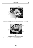
Note routing of VRCU cable prior to removal to ensure proper installation.
•
Remove cable ties and cushion clips as required.
3.
Remove VRCU cable (9) from cab instrument panel A (10) and vehicle.
NOTE
Perform Step (4) if bracket needs to be removed.
4.
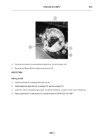
Remove four locknuts (11), washers (12), screws (13), and bracket (14) from cab instrument panel A (10).
Discard locknuts.
END OF TASK
INSTALLATION
NOTE
Perform Step (1) if bracket needs to be installed.
1.
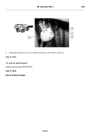
Install bracket (14) on cab instrument panel A (10) with four screws (13), washers (12), and locknuts (11).
NOTE
•
Route VRCU cable as noted prior to removal.
•
Install cable ties and cushion clips as required.
2.
Position VRCU cable (9) on vehicle and cab instrument panel A (10).
HWT3472
Back to Top


