TM-9-2320-361-20 - Page 317 of 1207
TM 9-2320-361-20
Section Ill. CLUTCH SYSTEM MAINTENANCE
3-9. CLUTCH SYSTEM MAINTENANCE INDEX
PARA.
TITLE
PAGE
NO.
NO.
3-10.
Clutch Control Linkage Maintenance
3-14
3-11.
Pedal Shaft Support Replacement
3-19
3-10. CLUTCH CONTROL LINKAGE MAINTENANCE
This task covers:
a. Removal
c.
Adjustment
b. Installation
INITIAL SETUP:
APPLICABLE MODELS
EQUIPMENT CONDITION
All
Parking brake set (TM 9-2320-361-10).
MATERIALS/PARTS
Four locknuts
Two woodruff keys
Chalk (Appendix C, Item 9)
REFERENCES (TM)
LO 9-2320-209-12-1
TM 9-2320-361-10
TM 9-2320-361-20P
Hood raised and secured (TM 9-2320-361-10).
Accelerator pedal, bracket, and rod removed
(para. 3-33).
Transmission power takeoff shift linkage removed
(vehicles with transmission PTO only)
(para. 13-20).
Hydraulic master cylinder removed (para. 8-10).
1.
2.
3.
4.
5.
6.
7.
8.
9.
10.
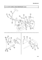
Remove clutch return spring (7) from clutch shaft lever (6) and frame (10).
Mark shaft of clutch pedal (3) with chalk next to remote control lever (14).
Remove screw (1), clutch pedal (3), and rubber bumper (2) from remote control lever (14).
Remove locknut (13), screw (4), remote control lever (14), and woodruff key (12) from pedal lever
shaft (11). Discard locknut (13) and woodruff key (12).
Remove locknut (9), screw (5), and rod (8) from clutch shaft lever (6). Discard locknut (9).
Remove locknut (26), screw (21), and remote control lever (20) with rod (8) from shaft (22). Discard
locknut (26).
NOTE
Do not remove spring loaded pin from clevis.
Pull pin (24) to one side of clevis (25) and remove remote control lever (20) from clevis (25).
Loosen nut (23) and remove clevis (25) and nut (23) from rod (8).
Remove locknut (18), screw (17), clutch shaft lever (6), and pedal lever shaft (11) from brake
lever (19) and shaft support (16). Discard locknut (18).
Remove woodruff key (15) from shaft (11). Discard woodruff key (15).
3-14
Back to Top


