TM-9-2320-361-20 - Page 977 of 1207
TM 9-2320-361-20
13-6. FRONT WINCH PROPELLER SHAFT REPLACEMENT
This task covers:
a. Removal
c. Installation
b. Inspection
INITIAL SETUP:
APPLICABLE MODELS
REFERENCES (TM)
All
LO 9-2320-209-12-1
MATERIALS/PARTS
TM 9-2320-361-10
TM 9-2320-361-20P
Two cotter pins
Four locknuts
EQUIPMENT CONDITION
GAA grease (Appendix C, Item 13)
Parking brake set (TM 9-2320-361-10).
NOTE
Place front winch control lever in LOW position to remove screws,
then in NEUTRAL position to gain access to remaining screws.
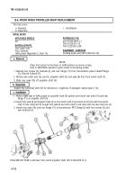
1. Remove four screws (3), locknuts (l), and rear flange (11) from transmission power takeoff flange
(2). Discard locknuts (l).
2. Remove two cotter pins (6), pin (5), propeller shaft (4), and yoke (8) from front winch shaft (7).
3. Slide rear yoke (10) off propeller shaft (4).
Inspect two universal joints (9) for looseness or roughness. If damaged, replace (para. 7-4).
1. Place a light coat of GAA grease on propeller shaft (4) splines and install rear yoke (10) and rear
flange (11) on propeller shaft (4).
2. Install front yoke (8) and propeller shaft (4) on front winch shaft (7) and aline pin (5) hole with front winch
shaft (7) hole. Install pin (5) through front yoke (8) and winch shaft (7) and secure with two new cotter pins (6).
3. Install rear yoke (10) and rear flange (11) to transmission PTO flange (2) with four screws (3) and
new locknuts (l).
FOLLOW-ON TASK: Lubricate front winch propeller shaft (LO 9-2320-209-12-1).
13-12
Back to Top


