TM-9-2320-361-20 - Page 979 of 1207
TM 9-2320-361-20
13-8. REAR WINCH CONTROL LEVER LINKAGE MAINTENANCE (M764)
This task covers:
a. Removal
b. Installation
INITIAL SETUP:
APPLICABLE MODELS
REFERENCES (TM]
M764
TM 9-2320-361-10
MATERIALS/PARTS
Four cotter pins
Locknut
TM 9-2320-361-20P
EQUIPMENT CONDITION
Parking brake set (TM 9-2320-361-10).
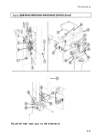
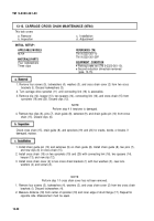
1. Remove cotter pin (19) and clevis pin (16) from control lever (17) and winch control rod (14). Discard
cotter pin (19).
2. Remove locknut (20), screw (15), and winch control lever (17) from bracket (18). Discard
locknut (20).
3. Remove cotter pin (4), clevis pin (7), and rod (14) from pivot bar (5). Discard cotter pin (4).
4. Remove two cotter pins (22) and (3), clevis pins (21) and (6), and winch control clevis (2) from
lever (1) and pivot bar (5). Discard cotter pins (22) and (3).
5. Remove jamnut (9), nut (8), washer (10), screw (13), washer (12), and pivot bar (5) from bracket (11).
NOTE
After nut has been tightened in step 1, ensure pivot bar moves
freely.
1. Install pivot bar (5) on bracket (11) with washer (12), screw (13), washer (10), nut (8), and
jamnut (9).
2. Connect clevis (2) to lever (1) and pivot bar (5) with two clevis pins (6) and (21) and new cotter
pins (3) and (22).
3. Adjust rod (14) to measure 58.13 in. (148 cm) from center of clevis (23) pin hole and center of
clevis (24) pin hole.
4. Install rod (14) to pivot bar (5) with clevis pin (7) and new cotter pin (4).
NOTE
After locknut has been tightened in step 5, ensure control lever
moves freely.
5. Install winch control lever (17) on bracket (18) with screw (15) and new locknut (20).
6. Connect winch control rod (14) to control lever (17) with clevis pin (16) and new cotter pin (19).
13-14
Back to Top


