TM-9-2320-361-24-1 - Page 203 of 1176
MALFUNCTION
TEST OR INSPECTION
CORRECTIVE ACTION
1. NO ALTERNATOR
OUTPUT
NOTE
• Voltage regulator is built into
alternator.
• If STE/ICE-R is available, perform
NG 50 Charging Circuit Tests
(WP 0018 00).
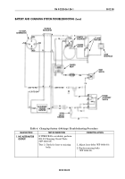
Test 1. Check for loose or missing
belts.
Test 2. Test charging system output
voltage.
NOTE
If vehicle is equipped with a slave
receptacle, check voltage at
receptacle.
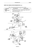
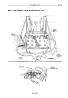
1. Open door of battery
compartment. Loosen two
thumbscrews and slide
batteries onto running board
(WP 0127 00).
2. Start engine
(TM 9-2320-361-10).
3. Set engine speed at
1200 RPM.
4. Turn vehicle headlights and
accessories to ON position.
5. Use multimeter to check
battery voltage. Charging
voltage on batteries should be
28.0 ± 0.2 VDC.
1. Adjust loose belts (WP 0084 00).
2. Replace missing belts
(WP 0084 00).
1. If battery voltage measures 24.0
VDC, alternator has no output. Go
to test 3 and check input voltage.
2. If battery voltage is between 24.0
and 26.0 VDC, alternator output is
weak. Go to test 3 and check input
voltage.
3. If battery voltage measures 28.0 ±
0.2 VDC and voltmeter on
instrument panel shows no voltage,
an electrical problem exists
between alternator and power
accessory switch. Go to
WP 0012 00, table 2, malfunction 1,
test 4, step 3.
4. If battery voltage measures
between 26.0 and 30.0 VDC, adjust
voltage regulator (WP 0085 00) in
alternator until voltage across
batteries is 28.0 ± 0.2 VDC. Go to
test step 6 and check regulator
stability.
TM 9-2320-361-24-1
0012 00
0012 00-19
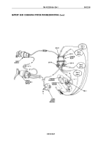
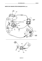
BATTERY AND CHARGING SYSTEM TROUBLESHOOTING (Contd)
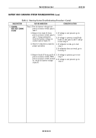
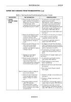
Table 3. Charging System (60 Amp) Troubleshooting Procedure.
Back to Top

