TM-9-2320-361-24-1 - Page 196 of 1176
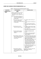
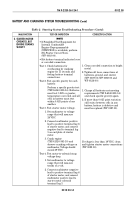
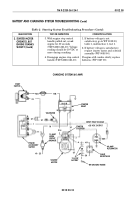
MALFUNCTION
TEST OR INSPECTION
CORRECTIVE ACTION
1. STARTER
WILL NOT CRANK
(Contd)
4. Remove leads 11 from pins A
and C and lead 1 from pin D.
With power accessory switch
in ON position, check
continuity between pins A and
B and between pins C and D.
5. Remove lead 74A from pin B
of start switch. With power
accessory switch in ON
position, turn start switch and
check for battery voltage at
pin B.
6. Remove lead 74 from pin A of
start switch, turn power
accessory switch to ON
position, and check for battery
voltage at pin B.
7. Attempt to start engine
(TM 9-2320-361-10).
8. Remove lead 74 from pin A
and lead 74A from pin B of
start switch. Turn start
switch and perform continuity
check between pins A and B.
Test 4. Check for battery voltage at
horn circuit breaker.
1. Remove lead 10 from horn
circuit breaker and check
battery voltage on contact
end.
2. Disconnect battery ground
cable (WP 0126 00).
Disconnect leads 11 from
power accessory switch and
check continuity of two leads
10 and lead 11.
1. If continuity is not found, replace
power accessory switch
(WP 0104 00). Check continuity of
new power accessory switch before
installation. Reinstall leads 11 in
pins A and C. Reinstall lead 27 in pin
B and lead 1 in pin D. Attempt to
start engine (TM 9-2320-361-10).
2. If starter does not crank engine, go to
test step 5.
1. If voltage is not present, go to step 6.
2. If voltage is present, perform
continuity check on lead 74A
3. If continuity is present, repair or
replace lead (WP 0090 00).
1. If voltage is not present, disconnect
lead 27 from power accessory switch
and check continuity between lead 27
and its connection to lead 74.
2. If continuity is not found, repair or
replace lead. Reinstall lead 74 into
pin A.
If starter does not engage engine, go to
test step 8.
1. If continuity is not found, replace
start switch (WP 0089 00).
2. Check continuity of new switch
before installation.
3. Reinstall lead 74A in pin B and lead
74 in pin A.
4. Turn start switch. Starter should
turn engine.
1. If battery voltage is not present, go to
test step 2.
2. If battery voltage is present, go to
test step 3.
1. If continuity is not present, repair or
replace leads 10 and 11 (WP 0090 00).
2. If continuity is present, reconnect
leads 10 and 11, and battery ground
cable (WP 0126 00). Go to test step 3.
TM 9-2320-361-24-1
0012 00
0012 00-12
BATTERY AND CHARGING SYSTEM TROUBLESHOOTING (Contd)
Table 2. Starting System Troubleshooting Procedure (Contd).
Back to Top

