TM-9-2320-361-24-1 - Page 204 of 1176
MALFUNCTION
TEST OR INSPECTION
CORRECTIVE ACTION
1. NO ALTERNATOR
OUTPUT
6. Check voltage regulator
stability.
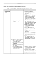
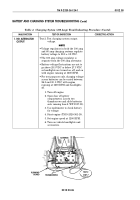
Test 3. Test input voltage to alternator.
1. Turn headlights to OFF
position. Stop engine.
2. Disconnect lead 1 from lead 568
at alternator.
3. Turn power accessory switch to
ON position.
4. Check for battery voltage at
contact end of lead 1. Voltage
should be 24.0 VDC.
5. If alternator voltage across
batteries cannot be adjusted to
28.0 ± 0.2 VDC, replace alternator
(WP 0085 00).
6. If battery voltage is greater than
30.0 VDC, first try to adjust voltage
regulator in alternator down to
28.0 VDC. If voltage regulator
voltage cannot be adjusted to 28.0
VDC, replace alternator (WP 0085
00).
1. Decrease engine speed to 1000
RPM with headlights in ON
position. Regulated battery voltage
should remain at 28.0 ± 0.2 VDC.
2. If battery voltage drops below
27.5 VDC, replace alternator
(WP 0085 00).
3. Increase engine speed to 2000
RPM. Regulated battery voltage
should remain at 28.0 ± 0.2 VDC.
4. If battery voltage increases above
28.5 VDC, replace alternator
(WP 0085 00).
5. Return engine speed to 1200 RPM.
6. Turn headlights on and off and
observe change in battery voltage.
7. If battery voltage changes more
than ± 0.5 VDC and does not
return quickly to 28.0 ± 0.2 VDC,
replace alternator (WP 0085 00).
1. If voltage is not present, open lead
or bad connection exists in input
circuit. Go to test 6.
2. If voltage is 24.0 VDC (normal),
remove access cover on top of
alternator to expose output terminal.
3. Reconnect lead 1 to lead 568. Go to
test step 5.
TM 9-2320-361-24-1
0012 00
0012 00-20
BATTERY AND CHARGING SYSTEM TROUBLESHOOTING (Contd)
Table 3. Charging System (60 Amp) Troubleshooting Procedure (Contd).
Back to Top

