TM-9-2320-361-24-1 - Page 207 of 1176
TM 9-2320-361-24-1
0012 00
0012 00-23
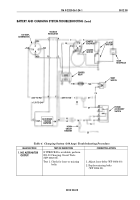
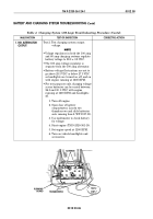
BATTERY AND CHARGING SYSTEM TROUBLESHOOTING (Contd)
Table 3. Charging System (60 Amp) Troubleshooting Procedure (Contd).
MALFUNCTION
TEST OR INSPECTION
CORRECTIVE ACTION
1. NO ALTERNATOR
OUTPUT
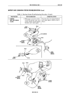
3. Check voltage at pin D of
power accessory switch.
Battery voltage should be
present.
4. With both ends of lead 1
disconnected, check
continuity.
1. If battery voltage is present, go to
WP 0012 00, table 3, malfunction 1,
test 6, step 4 and check continuity
of lead 1.
2. If voltage is not present, go to
WP 0012 00, table 2, malfunction 1,
test 4, step 8, to test continuity of
power accessory switch.
3. If continuity is present in power
accessory switch, go to
next step.
1. If continuity is present, reconnect
lead 1 to pin D of power accessory
switch. With power accessory
switch in ON position, battery
voltage should be present at lead 1.
2. If continuity is not present, repair
or replace lead 1 (WP 0090 00).
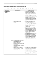
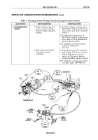
TEST 3
STEP 4
TEST 6
STEP 3
TEST 6
STEP 4
TEST 3
STEP 5
TEST 4
STEP 4
TEST 5
STEP 1
~
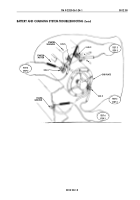
ALTERNATOR
NEGATIVE
LEAD
HORN
CIRCUIT
BREAKER
LUG 2
PIN 1
LUG 3
PIN 4
214
568
3
1
2
2
27
11
11
PIN B
PIN A
PIN D
STARTER MOTOR
PIN C
FRAME
GROUND
POWER
ACCESSORY
SWITCH
Back to Top

