TM-9-2320-361-34 - Page 497 of 764
TM 9-2320-361-34
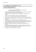
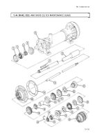
15-44. BRAKE, FEED, AND DRIVE CLUTCH MAINTENANCE
THIS TASK COVERS:
INITIAL SETUP
APPLICABLE MODELS
M764
TOOLS
General
mechanic’s tool kit (Appendix B, Item 1)
Mechanical puller kit (Appendix B, Item 22)
Lifting device
MATERIALS/PARTS
Six lockwashers (Appendix F, Item 125)
Four lockwashers (Appendix F, Item 138)
Twenty-two lockwashers (Appendix F, Item 127)
Four gaskets (Appendix F, Item 61)
Four gaskets (Appendix F, Item 63)
Gasket (Appendix F, Item 62)
Four O-rings (Appendix F, Item 172)
Shim set (Appendix F, Item 258)
Shim set (Appendix F, Item 259)
Shim set (Appendix F, Item 257)
Four woodruff keys (Appendix F, Item 277)
Woodruff key (Appendix F, Item 276)
Cotter pin (Appendix F, Item 6)
Seal (Appendix F, Item 224)
GAA
grease (Appendix C, Item 8)
Sealing compound (Appendix C, Item 19)
Safety wire (Appendix C, Item 31)
Lubricating oil, OE/HDO 30 (Appendix C, Item 13)
PERSONNEL REQUIRED
Two
REFERENCES (TM)
LO 9-2320-209-12-1
TM 9-214
TM 9-237
TM 9-2320-361-10
TM 9-2320-361-20
TM 9-2320-361-34P
EQUIPMENT CONDITION
.
Parking brake set (TM 9-2320-361-10).
●
Clutch
case drained (LO 9-2320-209-12-1).
. Earth boring machine removed (para. 15-35).
●
Main drive idler gear removed (para. 15-43).
●
Intermediate case removed (para. 15-42).
. Operation levers removed (TM 9-2320-361-20).
GENERAL SAFETY INSTRUCTIONS
.
Be prepared to support clutch and brake.
●
All personnel must stand clear during lifting
operations.
a. Disassembly
1.
2.
3.
4.
5.
6.
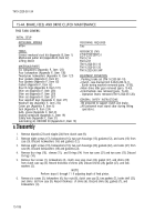
Remove dipstick (23) and nipple (24) from clutch case (9).
Remove eight screws (17), lockwashers (16), two cam housings (15), gaskets (12), and cams (13) from
case (9). Discard lockwashers (16) and gaskets (12).
Remove eight screws (19), lockwashers (18), two cam housings (20), gaskets (22), and cams (21) from
case (9). Discard lockwashers (18) and gaskets (22).
Remove four rings (10),
sleeves (11),
and O-rings (14)
from two cams (21) and two cams (13). Discard
O-rings (14).
Remove four screws (1), lockwashers (2), clutch case scap cover (26), gasket (27), and shims (28)
from clutch case cap (5). Record thickness of shims (28). Discard shims (28), gasket (27), and lock-
washers (2).
NOTE
Perform steps 6 through 11 if adjusting depth of feed pinion.
Remove six screws (3), lockwashers (4), four nuts (8), clutch case cap (5), two gaskets (7), brake shell (25),
and shims
(6) from case (9). Record thickness
of shims (6). Discard shims (6), gaskets (7), and
lockwashers (4).
15-186
Back to Top


