TM-9-2320-366-20-2 - Page 643 of 1632
TM 9-2320-366-20-2
TM 9-2320-366-20-2
TM 9-2320-366-20-2
TM 9-2320-366-20-2
TM 9-2320-366-20-2
2-1465
2-1465
2-1465
2-1465
2-1465
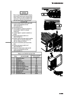
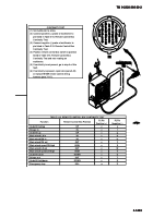
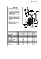
CONTINUITY TEST
Underlift fold up
Stinger in
Underlift up
Main winch RH in
Main winch RH out
Main winch speed RH high
Main winch LH out
Main winch speed LH high
Underlift down
Stinger out
Underlift fold down
Emergency stop
Function
Main winch LH in
UP
IN
UP
IN
IN
OUT
HIGH
OUT
HIGH
DOWN
OUT
DOWN
KILL
Remote Control Box Position
and Switch Number
Switch Pin
Positive (+)
9
7
7
7
7
7
7
7
7
7
7
7
7
Switch Pin
Negative (-)
2
3
4
6
8
11
12
13
14
16
15
17
10
REF
DES
S15
S15
S14
S13
S10
S8
S8
S9
S10
S11
S13
S14
S7
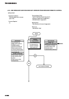
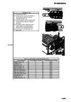
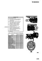
TABLE 2-16. REMOTE CONTROL BOX SWITCH CONTINUITY TEST
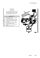
(1)
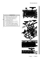
Open cover on remote control box.
(2)
Remove four screws, washers, and panel from
remote control box.
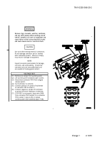
(3)
Set multimeter to ohms.
(4)
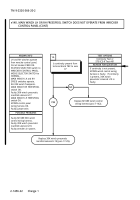
Connect positive (+) probe of multimeter to
pin listed in Table 2-16. Remote Control Box
Switch Continuity Test.
(5)
Connect negative (-) probe of multimeter to
pin listed in Table 2-16. Remote Control Box
Switch Continuity Test.
(6)
Position remote control box switch to position
listed in Table 2-16. Remote Control Box
Switch Continuity Test and note reading on
multimeter.
(7)
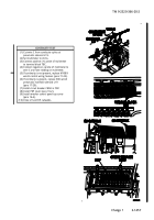
If continuity is not present, repair wire
(para 2-45) or replace remote control box
switch (para 7-35).
(8)
Install panel on remote control box with
four washers and screws.
Back to Top

