TM-9-2330-238-14
CHASSIS, SEMITRAILER: 6-TON, 4-WHEEL M295A1; SEMITRAILER, VAN: EXPANSIBLE, 6-TON, 4-WHEEL M313; SEMITRAILER, VAN: SHOP, FOLDING SIDES, 6-TON, 4-WHEEL M447 AND M447C; SEMITRAILER, VAN: REPAIR PARTS, SHOP EQUIPMENT, 6-TON, 4-WHEEL M749; SEMITRAILER, VAN: REPAIR PARTS STORAGE, 6-TON, 4-WHEEL M750
TECHNICAL MANUAL; OPERATOR’S, ORGANIZATIONAL, DIRECT SUPPORT, AND GENERAL SUPPORT MAINTENANCE MANUAL
JULY 1992
TM-9-2330-238-14 - Page 322 of 462
TM 9-2330-238-14
5-11. LANDING GEAR MAINTENANCE (EARLY MODEL).
This Task Covers:
a.
Removal
c.
Adjustment
b.
Installation
Initial Setup:
Equipment Conditions:
Materials/Parts:
●
Semitrailer
uncoupled
from
towing
vehicle
●
Two spring pins
(para 2-11).
●
Four self-locking nuts
Tools/Test Equipment:
●
Six retaining rings
●
Ten lubrication fittings
●
General mechanic’s tool kit
●
Thirty-seven lockwashers
●
Hydraulic jack
●
Jackstands
Personnel Required:
Two
●
Retaining ring pliers
a.
REMOVAL
1.
2.
3.
4.
5.
6.
7.
8.
9.
10.
11.
12.
5-20
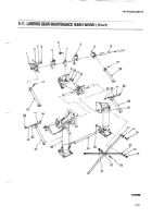
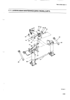
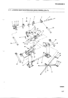
Chock wheels and raise front of chassis at front crossmember with jack until weight of semitrailer is off support
leg assemblies (26). Position jackstands under frame and lower semitrailer onto jackstands.
Remove four retaining rings
(22),
bearing sleeves (23), and two brace hinge pins (24) from left and right upper
and lower brace assemblies (18 and 25). Discard retaining rings.
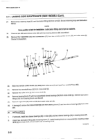
Drive out two spring pins (17) securing upper braces (18) to cross shaft (8) of actuator assembly (12). Discard
spring pins.
Remove 12 nuts (4), lockwashers (3), and capscrews (1) from two semitrailer brackets (2) on each side of frame.
Discard lockwashers.
Slide two semitrailer brackets (2) and upper braces (18) away from frame and off cross shaft (8).
Turn socket head setscrew (9) counterclockwise a minimum of two complete turns. DO NOT remove setscrew.
Block rear of actuating leg assembly (12).
Remove two capscrews (6), lockwashers (10), and nuts (11) from bearing block (7) and frame crossmember.
Discard lockwashers.
Remove cross shaft (8), two roller arms (5) and bearing block (7) as a unit by sliding the cross shaft to the left as
far as possible, then down to the right until unit is out of the frame holes.
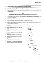
Remove two nuts (31), Iockwashers (30), and capscrews (35) from lower ends of diagonal braces (27), cross
tube assembly (36) and support leg assemblies (26), Discard Iockwashers.
Remove two capscrews (29) and lockwashers (28) from upper ends of diagonal braces (27) and support leg
assemblies (26). Remove diagonal braces. Discard lockwashers.
Remove capscrew (32), lockwasher (33), and nut (34) and separate diagonal braces (27). Discard
lockwashers.
Back to Top

