TM-9-2330-238-14
CHASSIS, SEMITRAILER: 6-TON, 4-WHEEL M295A1; SEMITRAILER, VAN: EXPANSIBLE, 6-TON, 4-WHEEL M313; SEMITRAILER, VAN: SHOP, FOLDING SIDES, 6-TON, 4-WHEEL M447 AND M447C; SEMITRAILER, VAN: REPAIR PARTS, SHOP EQUIPMENT, 6-TON, 4-WHEEL M749; SEMITRAILER, VAN: REPAIR PARTS STORAGE, 6-TON, 4-WHEEL M750
TECHNICAL MANUAL; OPERATOR’S, ORGANIZATIONAL, DIRECT SUPPORT, AND GENERAL SUPPORT MAINTENANCE MANUAL
JULY 1992
TM-9-2330-238-14 - Page 330 of 462
TM
9-2330-238-14
5-11.
LANDING
GEAR
MAINTENANCE
(EARLY MODEL)
(Con’t).
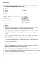
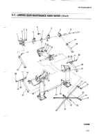
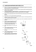
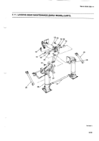
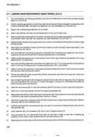
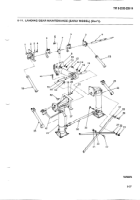
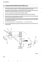
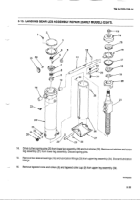
38.
Remove
plug
retaining
clips
(39), gib retaining
plugs
(40), and gibs
(38) from each support
leg assembly
(26).
39.
Aline
holes
in ends
of cross
shaft
(8) with holes
in upper
braces
(18) and install
two new
spring
pins
(17).
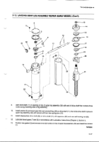
40.
Position
support
leg assemblies
(26) so upper
and lower
braces
(18 and 25) are in line.
NOTE
Center
of pin In brace hinge must be a minimum
of ~
In. (3.18
mm) below
normal center
Iine of brace
with
surface
of lower
brace
at contact
point. If necessary,
hand
file or
machine
upper
brace
surface
and/or
surface
of lower
brace.
41.
Install
pins
(24) at hinge
point
of each brace
and secure
each pin with two bearing
sleeves
(23) and two new
retaining
rings
(22).
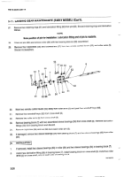
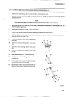
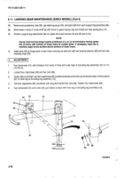
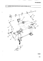
1.
Turn handcrank
(41) until
distance
from
ends
of inner and
outer
legs
of actuating
leg assembly
(12)
is
7 in.
(15.78 cm).
2.
Loosen
four capscrews
(56) and two nuts (58).
3.
If roller (64) is too high, turn two capscrews
(59) counterclockwise
until roller can be forced
down
on flat surface
(67) of inner leg of actuating
leg assembly
(12).
4.
Turn two
capscrews
(59) clockwise
until snug and tighten
two nuts (58). Tighten
four capscrews
(56).
5.
Turn handcrank
(41) until roller
(64) just makes
contact
with
inner leg of actuating
leg assembly
(12).
5-28
Back to Top

