TM-9-2330-238-14
CHASSIS, SEMITRAILER: 6-TON, 4-WHEEL M295A1; SEMITRAILER, VAN: EXPANSIBLE, 6-TON, 4-WHEEL M313; SEMITRAILER, VAN: SHOP, FOLDING SIDES, 6-TON, 4-WHEEL M447 AND M447C; SEMITRAILER, VAN: REPAIR PARTS, SHOP EQUIPMENT, 6-TON, 4-WHEEL M749; SEMITRAILER, VAN: REPAIR PARTS STORAGE, 6-TON, 4-WHEEL M750
TECHNICAL MANUAL; OPERATOR’S, ORGANIZATIONAL, DIRECT SUPPORT, AND GENERAL SUPPORT MAINTENANCE MANUAL
JULY 1992
TM-9-2330-238-14 - Page 338 of 462
TM
9-2330-238-14
5-13.
LANDING
GEAR
LEG ASSEMBLY
REPAIR
(EARLY MODEL)
(Con’t).
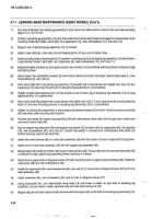
1.
2.
3.
4.
5.
6.
7.
8.
WARNING
Dry cleaning
solvent,
P-D-680,
is toxic and flammable.
Always wear protective
goggles
and gloves,
and use only in a well-ventilated
area.
Avoid contact
with skin, eyes,
and
clothes,
and DO NOT breathe
vapors.
DO NOT use near open flame
or excessive
heat.
The
solvent’s
flash
point
is 100°F-138°F
(38°C-59°C).
If you
become
dizzy
while
using cleaning
solvent,
Immediately
get fresh air and medical
help. if solvent
contacts
eyes,
Immediately
wash
your
eyes
and get medical
aid.
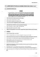
Clean
all parts with
dry cleaning
solvent
and dry thoroughly.
Inspect
screw
leg assembly
for damage,
wear, or corrosion.
Inspect
roller bearings
for pits, corrosion,
or wear and replace
if unserviceable
(Refer to TM 9-214
for care and
maintenance
of bearings).
Inspect
bevel
gears
for cracked,
chipped,
or worn
gear teeth.
Inspect
drive
shaft and intermediate
drive
shaft for cracks,
bends,
or breaks.
Check
contact
surface
of leveling
gib on lower
leg assembly
is smooth.
If not, remove
burrs with fine file and
abrasive.
Inspect
all mounting
hardware
for cracks,
bends,
or stripped
threads.
Replace
all defective
parts
as necessary.
1.
2.
3.
4.
5.
6.
7.
8.
5-36
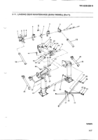
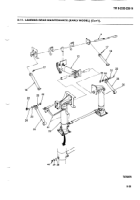
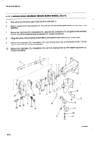
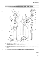
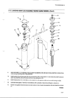
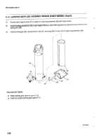
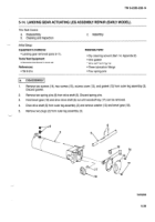
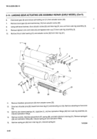
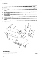
Install two
sleeve
bearings
(10) and new lubrication
fittings
(33) in upper
leg assembly
(34).
Position
screw leg assembly
(21) in lower leg assembly
(26) and install nut retainer (20). Secure nut retainer with
two new spring
pins
(25).
Install
thrust washer
bearing
(19) and ratchet
wheel
(18) on screw
leg assembly
(21).
NOTE
Control
cam is stamped
with the letter T on one side to indicate
the top. Ensure control
cam is assembled
accordingly.
Install
thrust roller
bearing
(15) and control
cam
(16) in clutch
case
(14) and secure
with retaining
ring (17).
Install
clutch
case
(14) on screw
leg assembly
(21).
Install
lower
leg assembly
(26) and screw
leg assembly
(21) in upper
lieg assembly
(34), taking
care
not to
damage
threads
on screw
leg assembly.
Install sleeve
bearing
(13), tapered
roller cup (9), tapered
cone and rollers (8), machine
key (5), and bevel gear
(7) on screw
lieg assembly
(21) and secure
with new self-locking
nut (4).
Tighten
self-locking
nut (4) just enough
to allow
screw
leg assembly
(21) to turn freely with a minimum
of end
play.
Back to Top

