TM-9-2330-238-14
CHASSIS, SEMITRAILER: 6-TON, 4-WHEEL M295A1; SEMITRAILER, VAN: EXPANSIBLE, 6-TON, 4-WHEEL M313; SEMITRAILER, VAN: SHOP, FOLDING SIDES, 6-TON, 4-WHEEL M447 AND M447C; SEMITRAILER, VAN: REPAIR PARTS, SHOP EQUIPMENT, 6-TON, 4-WHEEL M749; SEMITRAILER, VAN: REPAIR PARTS STORAGE, 6-TON, 4-WHEEL M750
TECHNICAL MANUAL; OPERATOR’S, ORGANIZATIONAL, DIRECT SUPPORT, AND GENERAL SUPPORT MAINTENANCE MANUAL
JULY 1992
TM-9-2330-238-14 - Page 336 of 462
TM
9-2330-238-14
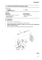
5-13.
LANDING
GEAR
LEG ASSEMBLY
REPAIR
(EARLY MODEL).
This
Task
Covers:
a.
Disassembly
c.
Assembly
b.
Cleaning
and Inspection
—
Initial
Setup:
Equipment
Conditions:
MateriaIs/Parts:
●
Landing
gear removed
(para 5-11).
●
Dry cleaning
solvent
(Item
14, Appendix
E)
●
Landing
gear gearbox
removed
(para 5-12).
●
One gasket
Tools/Test
Equipment:
●
Two lubrication
fittings
●
General
mechanic’s
tool
kit
●
Two self-locking
nuts
References:
●
Six spring
pins
. TM 9-214
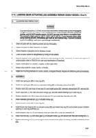
a.
DISASSEMBLY
NOTE
Use
this
task
to
disassemble
left
or
right
landing
gear
leg
assemblies.
Right
leg
assembly
Is shown.
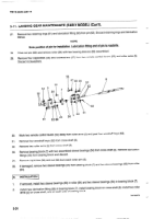
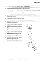
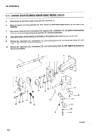
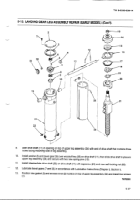
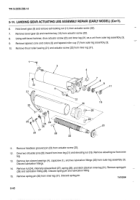
Remove
two spring
pins (28) from headless
straight
pin
(29).
Drive pin out of jack support
shoe (27) and remove
shoe
from
lower
leg assembly
(26). Discard
spring
pins.
Remove
four screws
(1), access
cover (2), and gasket
(3) from top of upper leg assembly
(34). Discard
gasket.
Remove
self-locking
nut (22), capscrew
(24), and intermediate
drive
shaft
(23) from
drive
shaft
(11). Discard
self-locking
nut.
Remove
two spring
pins
(12) from drive
shaft (11). Discard
spring
pins.
Hold
bevel
gear
(35), and turn drive
shaft (11) until woodruff
key (36) can be removed.
Drive drive
shaft
(11) out of upper
leg assembly
(34) and remove
bevel
gear
(35) and washer
(6).
Hold
bevel
gear
(7), and remove
self-locking
nut (4) from screw
leg assembly
(21). Discard
self-locking
nut.
Remove
plug
(30), spring
tension
clip
(31), and leveling
gib
(32) from upper
leg assembly
(34).
Using
a soft-face
hammer, drive screw
leg assembly
(21) down until machine
key (5) and bevel
gear (7) can be
removed.
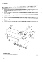
Remove
lower
leg assembly
(26) to include
sleeve
bearing
(13), screw
leg assembly
(21), nut retainer
(20),
thrust washer
bearing
(19), ratchet wheel
(18), retaining
ring (17), control
cam (16), thrust roller bearing
(15), and
clutch
case
(14).
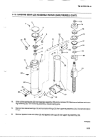
Remove
sleeve
bearing
(13), clutch case (14), thrust roller bearing
(15), control
cam (16), and retaining
ring (17)
as a unit from
screw
leg assembly
(21).
—--
Remove
retaining
ring (17), control
cam
(16), and thrust roller
bearing
(15) from
clutch
case
(14).
Remove
ratchet
wheel
(18) and thrust washer
bearing
(19) from
screw
leg assembly
(21).
5-34
w
Back to Top

