TM-9-2330-238-14
CHASSIS, SEMITRAILER: 6-TON, 4-WHEEL M295A1; SEMITRAILER, VAN: EXPANSIBLE, 6-TON, 4-WHEEL M313; SEMITRAILER, VAN: SHOP, FOLDING SIDES, 6-TON, 4-WHEEL M447 AND M447C; SEMITRAILER, VAN: REPAIR PARTS, SHOP EQUIPMENT, 6-TON, 4-WHEEL M749; SEMITRAILER, VAN: REPAIR PARTS STORAGE, 6-TON, 4-WHEEL M750
TECHNICAL MANUAL; OPERATOR’S, ORGANIZATIONAL, DIRECT SUPPORT, AND GENERAL SUPPORT MAINTENANCE MANUAL
JULY 1992
TM-9-2330-238-14 - Page 332 of 462
TM
9-2330-238-14
5-11.
LANDING
GEAR
MAINTENANCE
(EARLY MODEL)
(Con’t).
6.
7.
8.
9.
10.
11.
12.
13.
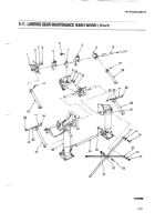
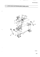
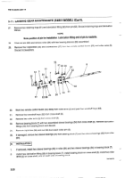
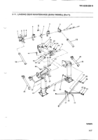
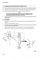
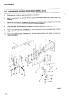
Rotate
each
lower
support
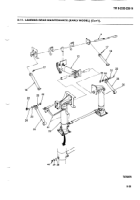
leg (26) and shoe
(66) until exposed
matching
groove
(65) of lower
support
leg is
7¼ in. (18.42
cm) long,
plus
or minus
~e in. (7.94 mm), with both
slots
in line with
semitrailer.
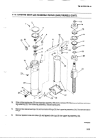
Install
gibs
(38), gib retaining
plugs
(40), and plug
retaining
clips
(39) in each
support
leg assembly
(26) and
matching
groove
(65). Ensure that gibs
are snug but do not bind
in matching
groove.
Lubricate
in accordance
with
Lubrication
Instructions
(Chapter
3, Section
l).
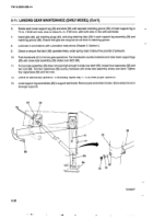
Check
to ensure
that latch
(68) operates
freely
under
spring
load
of about
five pounds
of pressure.
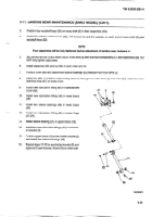
Push handcrank
(41) in for low gear operations.
Turn handcrank
counterclockwise
and raise lower support
legs
(26) until cross
tube
assembly
(36) slides
over latch
(68).
If cross tube assembly
(36) does
not raise high enough
to slide over latch (68), loosen
four capscrews
(56) and
two nuts (58). Turn two capscrews
(59) evenly
clockwise
until cross
tube
assembly
slides
over latch. Tighten
four capscrews
(56) and two
nuts.
Check for satisfactory
operation.
If necessary,
repeat step
11 to achieve
proper
operation.
Lower support
leg assemblies
(26) to support
semitrailer.
Remove jack and wheel chocks.
Store wheel chock
in
stowage
supports.
5-30
Back to Top

