TM-9-2330-238-14
CHASSIS, SEMITRAILER: 6-TON, 4-WHEEL M295A1; SEMITRAILER, VAN: EXPANSIBLE, 6-TON, 4-WHEEL M313; SEMITRAILER, VAN: SHOP, FOLDING SIDES, 6-TON, 4-WHEEL M447 AND M447C; SEMITRAILER, VAN: REPAIR PARTS, SHOP EQUIPMENT, 6-TON, 4-WHEEL M749; SEMITRAILER, VAN: REPAIR PARTS STORAGE, 6-TON, 4-WHEEL M750
TECHNICAL MANUAL; OPERATOR’S, ORGANIZATIONAL, DIRECT SUPPORT, AND GENERAL SUPPORT MAINTENANCE MANUAL
JULY 1992
TM-9-2330-238-14 - Page 328 of 462
TM
9-2330-238-14
5-11.
LANDING
GEAR
MAINTENANCE
(EARLY MODEL)
(Con’t).
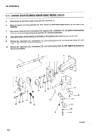
17.
18.
19.
20.
21.
22.
23.
24.
25.
26.
27.
28.
29.
30.
31.
32.
33.
34.
35.
36.
37.
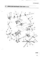
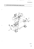
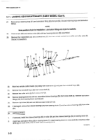
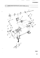
Turn drive shaft (44) of actuating
leg assembly (12)
by hand until distance
from ends of inner and outer actuating
legs
is 5 in. (12,70 cm).
Position
actuating
leg assembly
(12) and drive shaft (44) in frame with forward
end against
crossmember.
Aline
mounting
holes
and install,
hand tight,
two capscrews
(13), new Iockwashers
(14), and nuts (15).
Support
rear of actuating
leg assembly (12)
on blocks.
Install
cross
shaft
(8), roller
arms (5) and bearing
block
(7) as a unit in frame
holes.
Aline mounting holes in bearing
block (7)
and rear mounting
bracket
of actuating
leg assembly (12)
with holes in
crossmember.
Install,
hand tight,
two capscrews
(6), new Iockwashers
(10), and nuts (11).
Slide
semitrailer
brackets
(2) and upper braces
(18) on ends of cross
shaft (8) with flat surface
of braces,
hinge
end facing
down.
Aline holes
in two semitrailer
brackets
(2) with holes
In frame and install,
hand tight, twelve
capscrews
(1), new
Iockwashers
(3), and nuts (4).
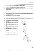
Aline
drive
shaft (44) in actuating
leg assembly
(12) parallel
with crossmember
and tighten
two nuts (15) and
capscrews
(13) securing
forward
end of actuating
leg assembly
to crossmember.
Tighten
socket
head
setscrew
(9) until flat surface
at top
of inner leg of actuating
leg assembly
(12) is snug
against
bottom
of crossmember.
Aline
cross
shaft (8) parallel
with crossmember
and tighten
two nuts (11) and capscrews
(6) securing
bearing
block
(7) and rear mounting
bracket
of actuating
leg assembly
(12) to crossmember.
Tighten
12 nuts (4) and capscrews
(1) securing
two semitrailer
brackets
(2) to frame. Check to ensure cross shaft
(8) turns freely
after securing
each bracket.
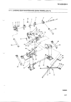
Position
and install
left support
leg assembly
(26) with intermediate
drive shaft (16) through
hole in frame and
over end of drive
shaft (44).
Secure
support
leg assembly
(26) and support
leg bracket
(37) to frame with six capscrews
(42), two spacers
(19), new
Iockwashers
(20), and nuts (21). Ensure that weight
is relieved
from
intermediate
drive
shaft
(16)
before
securing
support
leg assembly.
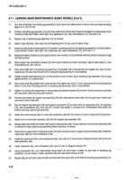
Install two
lower
braces
(25) on cross
tube assembly
(36) with flat surface
of brace
hinge
ends facing
down.
Install
end of cross
tube
assembly
(36) into left support
leg assembly
(26).
Repeat steps 28 and 29 and install right support
leg assembly
(26). Ensure right end of cross tube assembly
(36)
is installed
in right support
leg assembly
before
securing
it to frame.
Aline holes in upper ends of diagonal
braces
(27) with mounting holes in support
leg assemblies
(26), Install two
capscrews
(29) and new Iockwashers
(28).
Install two capscrews
(35), new Iockwashers
(30), and nuts (31) in lower ends of diagonal
braces
(27) and cross
tube
assembly
(36).
Install
capscrew
(32), new Iockwasher
(33), and nut (34) in diagonal
braces
(27).
Using
handcrank
(41), turn
intermediate
drive
shaft
(16) until
holes
in shafts
on right
side
of actuating
leg
assembly
(12) are alined.
Install
capscrew
(45) and new self-locking
nut (43).
Repeat step 36 to install capscrew
(45) and new self-locking
nut (43) on left side of actuating
leg assembly
(12).
5-26
Back to Top

