TM-9-2330-335-14-P - Page 548 of 640
TM 9-2330-335-14&P
0096-6
0096
MECHANICAL RELEASE OF SPRING BRAKE (GOLD SEAL) - CONTINUED
Pressurized Parking Brake Caging Recommendations
00096
1.
DO NOT use a high-speed and/or power-driven impact wrench to cage brake.
2.
Use air pressure (100 to 120 psi) in the chamber to collapse the compression spring before turning the release tool nut
with a hand wrench. Proper caging will be complete when a slight resistance is felt after turning the release tool nut.
CAUTION
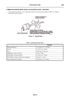
To ensure the compression spring is fully caged, the release tool length (X dimension) (Figure 6)
should measure as shown in Table 1.
END OF TASK
COMBINATION SPRING BRAKE INSTALLATION INSTRUCTIONS
00096
Installation Preparation
00096
1.
Spring brake must be caged prior to performing installation procedures. If brake is not caged,
Mechanical
Release of Spring Brake (Gold Seal)
in this work package for safety instructions and mechanical release of
spring brake.
2.
In an effort to maximize the life of Haldex Anchorlok spring brakes, Haldex Neway recommends the following brake
mounting guidelines when installing Haldex Anchorlok spring brakes on your vehicle(s).
Cut Push Rod to Correct Installation Length
00096
WARNING
Place blocks under wheels to prevent vehicle roll-away before removing spring brake actuators.
Failure to comply could cause injury or death to personnel.
CAUTION
Before installing a new combination spring brake, it is necessary to determine the correct service
push rod length to ensure proper alignment for efficient operation of the spring brake (Figure 7).
Failure to comply could cause damage to equipment.
NOTE
•
Units are furnished with a universal fully threaded push rod and must be cut to the correct length.
•
If spring brake unit being replaced is not available to take measurements from, follow the
procedures listed under step 5 below.
1.
Remove worn or non-functional spring brake unit from vehicle. Determine manufacturer and model of unit to be
replaced. Refer to that manufacturer’s service manual for caging and removal instructions.
2.
Make sure the spring chamber of the removed actuator is fully released (power spring caged) and the service brake push
rod is fully retracted to zero stroke position (i.e., brake fully released).
Back to Top


