TM-9-2330-335-14-P - Page 551 of 640
0096-9
TM 9-2330-335-14&P
0096
COMBINATION SPRING BRAKE INSTALLATION INSTRUCTIONS - CONTINUED
NOTE
•
Setup stroke is only to establish push rod length.
•
For a typical Type 30 spring brake, if dimension “B” (Figure 9) = 5.0 in., setup stroke = 1-1/2 in.
(Table 3). The push rod length from mounting face to centerline of main clevis pin should measure:
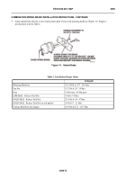
5 minus 1-1/2 = 3-1/2 in. with the spring brake caged (Figure 10).
6.
Before marking push rod to be cut on new unit, be sure the spring chamber is caged and the push rod is fully retracted to
the zero stroke position. Refer to
Mechanical Release of Spring Brake (Gold Seal)
in this work package.
NOTE
When determining the push rod cut-off length, the length of the threaded rod protruding between
the clevis legs must not exceed 3/16 in. to insure no interface with the operation of the stack
adjuster (Figure 7).
7.
Thread clevis jam nut past the mark on push rod. Align bottom edge of nut with mark to use as a guide for cutting. Use a
sharp hack-saw and cut push rod on the mark.
8.
After cutting rod, thread jam nut off to clean up threads.
Back to Top


