TM-9-2330-335-14-P - Page 556 of 640
TM 9-2330-335-14&P
0096-14
0096
COMBINATION SPRING BRAKE INSTALLATION INSTRUCTIONS - CONTINUED
Verify Proper Installation
00096
1.
With the brake applied, the following conditions must occur:
a.
Push rod 90 degrees to the centerline of slack adjuster.
b.
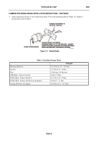
Push rod 90 degrees to the mounting face of the spring brake (Figure 17).
Figure 17.
Sealed Brake.
096
* Stroke length measured by applying parking brake or 60 PSIG service brake application.
** Long Stroke.
† Typical setup stroke values.
Notice:
For special applications, consult vehicle, brake or slack adjuster manufacturers.
Table 3.
Stroke Values.
Chamber Type
Available Stroke
(Inches)
Recommended Chamber Stroke Range
Set-Up Stroke Ap-
plied Braked*†
Minimum
Maximum
09
1-3/4 in.
(Should be as short
a stroke as possible
without brake
dragging.)
-1 in.
1-3/8 in.
12
1-3/4 in.
-1 in.
1-3/8 in.
16
2-1/4 in.
-1-1/2 in.
1-3/8 in.
20
2-1/4 in.
-1-1/2 in.
1-3/8 in.
20XLS**
3 in.
-2-1/4 in.
1-3/4 in.
24
2-1/4 in.
-1-1/2 in.
1-3/8 in.
24LS**
2-1/2 in.
-1-3/4 in.
1-1/2 in.
24XLS**
3 in.
-2-1/4 in.
1-3/4 in.
30
2-1/2 in.
-1-3/4 in.
1-1/2 in.
30LS**
3 in.
-2-1/4 in.
1-3/4 in.
36
3 in.
-2-1/4 in.
1-3/4 in.
447-0234
Back to Top


