TM-9-2330-335-14-P - Page 555 of 640
0096-13
TM 9-2330-335-14&P
0096
COMBINATION SPRING BRAKE INSTALLATION INSTRUCTIONS - CONTINUED
Attach Clevis and Air Lines
00096
1.
Thread jam nut back onto the push rod a sufficient length to allow assembly of the clevis.
2.
Thread clevis onto the push rod. Clevis from removed unit may be reused provided clevis pin hole is not worn. Adjust
clevis to the same “Z” dimension as measured from the removed unit (Figure 8).
3.
Hold clevis to prevent it from turning and tighten jam nut against clevis to torque specifications (Table 2). Clevis must be
adjusted so that it has full thread engagement on the push rod (from flush to 3/16 in. protrusion) (Figure 7).
4.
Connect the service and emergency air lines to the proper air ports. Torque to specifications listed in Table 2.
5.
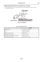
Connect clevis to the slack adjuster using clevis and cotter pins (Figure 15), and uncage the spring brake. Refer to
uncaging procedures.
Figure 15.
Sealed Brake.
096
CAUTION
If push rod is not long enough to reach slack adjuster mounting hole, DO NOT physically pull push
rod out to reach mounting hole. Doing so could cause damage to equipment.
6.
Adjust the slack adjuster to the listed setup stroke (Table 3) (Figure 16).
Figure 16.
Sealed Brake.
096
END OF TASK
447-0232
447-0233
Back to Top


