TM-9-2330-335-14-P - Page 549 of 640
0096-7
TM 9-2330-335-14&P
0096
COMBINATION SPRING BRAKE INSTALLATION INSTRUCTIONS - CONTINUED
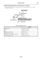
Figure 7.
Sealed Brake.
096
3.
Measure and record the “Y” and “Z” dimensions from unit to be replaced (Figure 8).
a.
“Y” dimension = Dimension from bottom of actuator to end of piston rod.
b.
“Z” dimension = Dimension from bottom of actuator to centerline of clevis pin.
4.
Take “Y” dimension (Figure 8) from the removed unit and mark push rod of new unit to be cut.
Figure 8.
Sealed Brake.
096
447-0225
447-0224
Back to Top


