TM-9-2330-342-23-P - Page 283 of 1348
3.
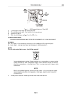
Connect button probe cable red lead to wire 1008B.
4.
Connect button probe cable black lead to a known good ground.
5.
Have assistant turn engine start switch to ON. Refer to vehicle Operator's manual (WP
0190).
6.
Have assistant turn ON lights. Refer to vehicle Operator's manual (WP
0190).
7.
Perform ICE Test 89.
8.
Meter should display a reading between 22 and 28 vdc.
CONDITION/INDICATION
Are 22 to 28 vdc measured on wire 1008B/21 at LED composite light?
DECISION
Voltage OK - Replace LED composite light (WP
0056). Go to (Step 12 - Do taillights operate?) to verify problem is
solved.
Voltage Faulty - Go to (Step 5 - Are 22 to 28 vdc measured on wire 1008B at rear junction box?).
STEP 5
Are 22 to 28 vdc measured on wire 1008B at rear junction box?
WARNING
Remove all jewelry such as rings, ID tags, bracelets, etc. prior to working on or around vehicle.
Jewelry and tools can catch on equipment, contact positive electrical circuits, and cause a
direct short, severe burns, or electrical shock. Failure to comply may result in injury or death
to personnel.
1.
Have assistant turn OFF lights. Refer to vehicle Operator's manual (WP
0190).
2.
Have assistant turn engine start switch to OFF. Refer to vehicle Operator's manual (WP
0190).
3.
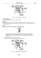
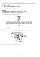
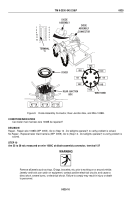
Connect wire 1008B to LED composite light wire 21.
4.
Remove cover from rear junction box (WP
0058).
COVER
REAR JUNCTION
BOX
C
L
O
S
E
O
P
E
N
WIRE 1008B
1435
1435
1008B
1012B
1680C
1678C
1003C
1004C
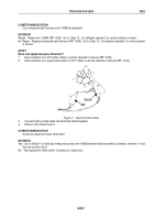
Figure 5.
Rear Junction Box and Wire 1008B.
5.
Connect button probe cable red lead to rear junction box terminal, wire 1008B.
6.
Connect button probe cable black lead to a known good ground.
7.
Have assistant turn engine start switch to ON. Refer to vehicle Operator's manual (WP
0190).
8.
Have assistant turn ON lights. Refer to vehicle Operator's manual (WP
0190).
TM 9-2330-342-23&P
0025
0025-5
Back to Top


