TM-9-2330-342-23-P - Page 392 of 1348
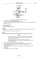
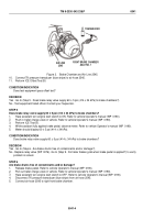
QUICK RELEASE
VALVE
AIR
LINE
2660
TRANSDUCER
Figure 1.
Quick Release Valve and Air Line 2660.
2.
Disconnect air hose 2660 from quick release valve.
3.
Connect TK pressure transducer (blue stripe) to air hose 2660.
4.
Connect TK pressure test cable to MSD/ICE test equipment (WP
0004) and to TK pressure transducer (blue
stripe).
5.
Perform ICE Offset Test 50.
CONDITION/INDICATION
Does test equipment pass offset test?
DECISION
Yes - Go to (Step 2 - Is load sensing valve adjusted correctly and supplying 30 to 125 ± 5 psi (207 to 861 ± 34
kPa)?).
No - Test equipment failed offset. Contact your Supervisor.
STEP 2
Is load sensing valve adjusted correctly and supplying 30 to 125 ± 5 psi (207 to 861 ± 34 kPa)?
NOTE
•
When rod is disconnected from the valve, it should hang freely without interference
from other components. During testing of load sensing valve, control rod must be
able to simulate a no load condition.
•
Trailer air system pressure must be 125 ± 5 psi (861 ± 34 kPa) to begin
troubleshooting the brake system. If the sir system cannot be maintained, refer to Air
System Troubleshooting.
1.
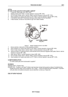
Disconnect load sensing valve control rod from axle (WP
0080).
2.
Have assistant turn engine start switch to ON. Refer to vehicle Operator's manual (WP
0190).
3.
Push in trailer charge valve in vehicle. Refer to vehicle Operator's manual (WP
0190).
4.
Perform ICE Test 50.
5.
While assistant fully applies brake pedal, push up on control rod. Refer to vehicle Operator's manual
(WP
0190).
6.
Observe meter.
7.
Meter should display 125 ± 5 psi (861 ± 34 kPa).
TM 9-2330-342-23&P
0041
0041-2
Back to Top


