TM-9-2330-342-23-P - Page 387 of 1348
3.
While assistant fully applies brake pedal, pull down on control rod and observe meter. Refer to vehicle
Operator's manual (WP
0190).
4.
Meter should display 30 ± 5 psi (207 ± 34 kPa).
CONDITION/INDICATION
Is load sensing valve adjusted correctly and supplying 30 to 125 ± 5 psi (207-861 ± 34 kPa)?
DECISION
Yes - Go to (Step 5 - Does test equipment pass offset test?).
No - Replace load sensing valve (WP
0080). Go to (Step 7 - Do service brakes apply correctly?) to verify problem
is solved.
STEP 5
Does test equipment pass offset test?
1.
Release brake pedal. Refer to vehicle Operator's manual (WP
0190).
2.
Pull out trailer charge valve in vehicle. Refer to vehicle Operator's manual (WP
0190).
WARNING
If air lines are disconnected when they are under 125± 5 psi (862± 34 kPa) pressure, they
can whip around. Care should be exercised when disconnecting an air hose that is thought
to be under pressure. Be sure to wear proper eye protection. Failure to comply may result in
injury or death to personnel.
3.
Have assistant turn engine start switch to OFF. Refer to vehicle Operator's manual (WP
0190).
4.
Disconnect air hose 2660 from TK pressure transducer (blue stripe).
5.
Connect air hose 2660 to quick release valve.
6.
Connect control rod to axle (WP
0080).
7.
Adjust load sensing valve (WP
0080).
8.
Drain trailer air system. Refer to TM 9-2330-342-10 (WP
0190).
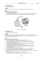
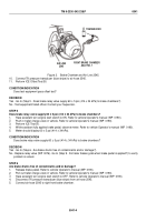
FRONT
RELAY
VALVE
AIR LINE
2639
TRANSDUCER
Figure 5.
Front Relay Valve and Air Line 2639.
9.
Disconnect air hose 2639 from front brake relay valve.
10.
Connect air hose 2639 to TK pressure transducer (blue stripe).
TM 9-2330-342-23&P
0040
0040-5
Back to Top


