TM-9-2330-342-23-P - Page 650 of 1348
INSTALLATION - Continued
1
2
3
4
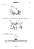
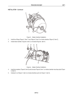
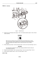
Figure 7.
Brake Chamber Installation.
6.
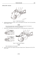
Install brake chamber push rod (Figure 7, Item 3) on slack adjuster clevis (Figure 7, Item 1) by turning locking
collar nut (Figure 7, Item 2).
NOTE
Push rod must be within 0.25 in. (6.35 mm) of the opening in the clevis. The rod must also
not extend more than 0.125 in. (3.17 mm) through the clevis.
7.
Check position of slack adjuster clevis (Figure 8, Item 1) on brake chamber push rod (Figure 8, Item 3).
1
MAXIMUM 0.25 in.
(6.35 mm)
MAXIMUM 0.125 in.
(3.17 mm)
2
3
4
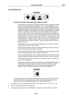
Figure 8.
Brake Chamber Installation.
NOTE
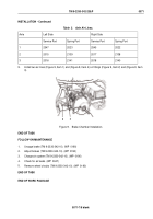
Refer to Table below for air line numbers.
8.
Turn jam nut (Figure 8, Item 4) against locking collar nut (Figure 8, Item 2). Tighten jam nut to 20 to 30 lb-ft
(27 to 41 N·m).
TM 9-2330-342-23&P
0071
0071-6
Back to Top

