TM-9-2330-342-23-P - Page 649 of 1348
INSTALLATION - Continued
1
2
3
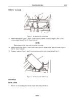
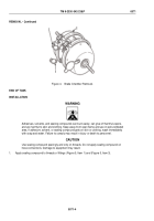
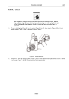
Figure 5.
Brake Chamber Installation.
2.
Install two fittings (Figure 5, Item 1) and (Figure 5, Item 3) on brake chamber (Figure 5, Item 2).
3.
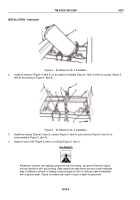
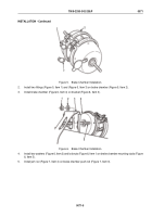
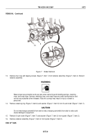
Install brake chamber (Figure 6, Item 4) on bracket (Figure 6, Item 3).
1
2
3
4
5
Figure 6.
Brake Chamber Installation.
4.
Install two washers (Figure 6, Item 2) and locknuts (Figure 6, Item 1) on brake chamber mounting studs (Figure
6, Item 5).
5.
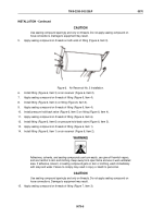
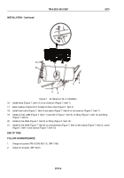
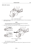
Install jam nut (Figure 7, Item 4) on brake chamber push rod (Figure 7, Item 3).
TM 9-2330-342-23&P
0071
0071-5
Back to Top

