TM-9-2330-342-23-P - Page 933 of 1348
INSTALLATION
NOTE
•
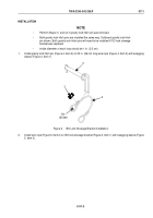
Perform Steps (1) and (2) if gravity lock hitch pin was removed.
•
Both gravity lock hitch pins are installed the same way. Outboard gravity lock hitch
pin shown. Both gravity lock hitch pins will need to be installed if ISO lock stowage
bracket was replaced.
•
Inside diameter of each loop should be 1 in. (2.5 cm).
1.
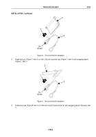
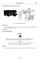
Install gravity lock hitch pin (Figure 4, Item 2) on 22 in. (56 cm) long wire rope (Figure 4, Item 3) with swagging
sleeve (Figure 4, Item 1).
2
3
1
1 in.
(2.5 cm)
Figure 4.
ISO Lock Stowage Bracket Installation.
2.
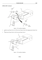
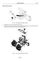
Install wire rope (Figure 5, Item 2) on ISO lock stowage bracket (Figure 5, Item 1) with swagging sleeve (Figure
5, Item 3).
TM 9-2330-342-23&P
0111
0111-3
Back to Top

