TM-9-2330-356-14
SEMITRAILER, TANK: 5000 GALLON, BULK HAUL, SELF LOAD/UNLOAD M967 AND M967A1; SEMITRAILER, TANK: 5000 GALLON, FUEL DISPENSING, AUTOMOTIVE M969 AND M969A1; SEMITRAILER, TANK: 5000 GALLON, FUEL DISPENSING, UNDER/OVERWING AIRCRAFT M970 AND M970A1
TECHNICAL MANUAL; OPERATOR’S, UNIT, DIRECT SUPPORT, AND GENERAL SUPPORT MAINTENANCE MANUAL
OCTOBER 1990
TM-9-2330-356-14 - Page 190 of 528
TM 9-2330-356-14
CAUTION
With preheater switch in the PREHEAT
position, 12V DC Is applied to manifold
heaters. Do not handle manifold heaters with
preheater switch in the PREHEAT position.
b.
Test.
Remove electrical leads to manifold heaters.
Use ohmmeter to test for continuity from terminal of
manifold heater to ground. Open circuit indicates faulty
manifold heater.
c.
Removal.
(1) Disconnect negative battery cable from
battery (fig. 4-37).
(2) Open engine door panel (fig. 4-101).
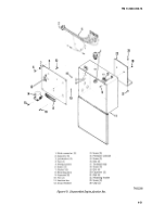
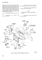
(3) Disconnect five electrical leads (1,2,3,4, and
5, fig. 4-32) from manifold heaters by removing nuts (6).
(4) Remove connecting bar (7).
(5) Unscrew manifold heaters (8) from air intake
manifold (9).
d.
Installation.
(1) Screw manifold heaters (8, fig. 4-32) into air
intake manifold. Tighten to 10-15 lb.-ft.
(2) Reinstall connecting bar (7), electrical leads
(1 through 5), and nuts (6) to manifold heaters.
(3) Close engine cover panel.
(4) Connect negative battery cable to battery
(fig. 4-37).
4-21.
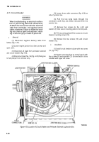
Glow Plugs
WARNING
TA099788
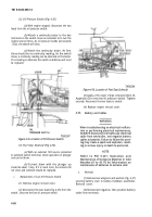
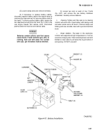
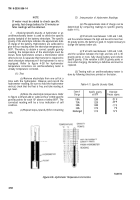
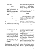
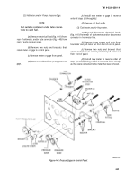
Figure 4-33. Glow Plugs.
CAUTION
With preheater switch In the PREHEAT
position, 12V DC Is applied to the glow plug
body. Do not handle glow plug with preheater
switch In the PREHEAT position.
b.
Test.
Remove electrical lead to glow plug. Use
ohmmeter to test for continuity from terminal of glow
plug and ground. Open circuit indicates bad glow plug.
c.
Removal.
Disconnect negative battery cable at
battery. Disconnect lead to glow plug. Unscrew glow plug
and remove it from cylinder head. Remove gasket with a
hooked wire, then replace.
d.
Installation.
If gasket has been removed, place
new gasket over glow plug. Coat plug threads with
anti-seize compound (item 6, Appendix E), and screw glow
plug into cylinder head. Tighten glow plug to 10-15 Ib.-ft.
Connect electrical lead to plug. Connect negative battery
lead to battery.
4-22. High Temperature
Switch, Oil Pressure
Switch, and Fuel Stop Solenoid
WARNING
When troubleshooting an electrical malfunc-
tion or performing electrical maintenance,
When troubleshooting an electrical malfunc-
ALWAYS disconnect Intervehicular electrical
tion or performing electrical maintenance,
cable from semitrailer, and negative battery
ALWAYS disconnect Intervehicular electrical
cables at batteries. Failure to follow this warn-
cable from semitrailer, and negative battery
ing may create a spark and explosion, result-
cables at batteries. Failure to follow this warn-
ing In serious injury or death to personnel.
ing may create a spark and explosion, result-
ing in serious injury or death to personnel.
a.
Inspection.
Inspect glow plugs (fig. 4-33) for
a.
General.
physical damage. Check that electrical lead to glow plug is
clean and tight. Check for leakage, indicated by oily
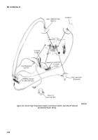
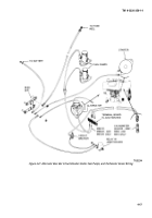
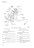
(1) The high temperature switch (fig. 4-34) is
residue, where glow plug enters cylinder head.
mounted on the engine just below the exhaust manifold on
4-5 4
Back to Top

