TM-9-2330-356-14
SEMITRAILER, TANK: 5000 GALLON, BULK HAUL, SELF LOAD/UNLOAD M967 AND M967A1; SEMITRAILER, TANK: 5000 GALLON, FUEL DISPENSING, AUTOMOTIVE M969 AND M969A1; SEMITRAILER, TANK: 5000 GALLON, FUEL DISPENSING, UNDER/OVERWING AIRCRAFT M970 AND M970A1
TECHNICAL MANUAL; OPERATOR’S, UNIT, DIRECT SUPPORT, AND GENERAL SUPPORT MAINTENANCE MANUAL
OCTOBER 1990
TM-9-2330-356-14 - Page 198 of 528
TM 9-2330-356-14
Figure
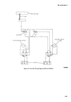
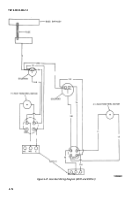
4-41.
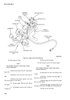
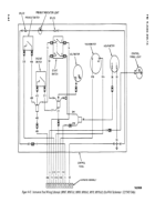
Engine Control Panel Wiring
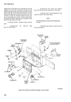
(4) Filter/Separator Gage.
NOTE
Put suitable container under tube connec-
tions to catch fuel.
(a)
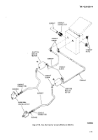
Disconnect lines from 90° tube elbows
(fig. 4-40)
(b)
Remove lens and cover from front of
gage.
(c)
Remove two screws, washers, and nuts
that secure gage to control panel.
(d)
from gage.
(e)
through
(d).
Remove gage. Remove both elbows
Install gage in reverse order of steps
(a)
TA099796
(f)
Clean up all fuel spills.
(5)
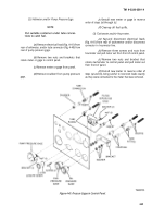
FueI Pressure and/or Oil Pressure Gages.
NOTE
Put suitable container under tube connec-
tions to catch fuel.
(a)
Disconnect line from tube fitting at rear
of gage.
(b)
Remove coupling securing gage to
bracket on control panel.
(c)
Remove gage and four washers through
front of control panel.
(d)
Install new gage in reverse order of
(a)
through (c). Be sure to shim gage with existing washers.
(e)
Clean up all fuel spills.
4-62
Back to Top

